
From Donor Part or CAD File to a Buildable Composite Component
Pricing should separate engineering and tooling, the prototype or first article, production, testing, packaging and shipping.
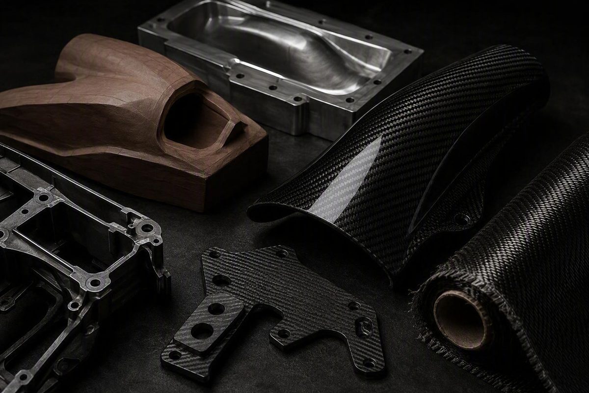
From donor part or CAD file to a buildable composite component
Ordering carbon fiber custom parts is not simply a matter of asking a shop to “make this in carbon.” A successful project starts by defining what the component must do, how it will be loaded, where it must fit, what environment it will face, how many copies are needed, and how the finished work will be accepted.
Those decisions determine whether carbon fiber is appropriate at all. They also shape the laminate, tooling, manufacturing route, inspection plan, price, and schedule. A cosmetic cover presents a very different engineering problem from a suspension bracket, medical-device component, or load-bearing aerodynamic surface.
A useful quote package should not attempt to prescribe every ply before a specialist reviews the project. It should give prospective fabricators enough reliable information to propose—and clearly accept responsibility for—their part of a buildable solution.
What “custom” means—and what it does not
A genuinely custom component is designed, digitized, adapted, or reproduced for customer-specific geometry and requirements. The work may begin with an existing physical part, a drawing, a CAD model, or a concept that still needs engineering. Depending on scope, it can involve scanning, surface reconstruction, new CAD, laminate development, plugs, molds, machining fixtures, prototypes, inspection methods, and validation.
That differs from selecting a predefined product for a listed vehicle or application. Trufiber, for example, presents vehicle-specific forged-carbon appearance parts; its collection page does not establish a one-off engineering service. RSI c6 likewise lists predefined forged-carbon products for selected vehicles rather than documenting a process for engineering unique customer components.
“Made to order” is not necessarily “fully custom.” A seller may manufacture a standard design only after purchase, offer a choice of dimensions or finish, or adapt a predefined product. That can be useful customization, but it does not automatically include new CAD, customer-owned tooling, laminate engineering, or application-specific testing.
Faircloth Composites advertises one-off work, plug and buck fabrication, mold making, production parts, CAD creation from a complete drawing, and reproduction of an existing part in another material. These are vendor-described capabilities that still need to be confirmed for the proposed geometry and risk level. Its page also displays a nominal $1 listing while directing customers to request actual project pricing, so that amount is a placeholder rather than the price of a unique part (Faircloth Composites).
In automotive work, one supplier may offer a donor-part arrangement that another does not. P1 Motor Cars says customers may send the original part or pay an added amount for the company to source one before recreating it. That is a specific option advertised by P1 Motor Cars, not a service to assume from every fabricator.
The material category must also be explicit:
-
Continuous-fiber laminates: Woven cloth, unidirectional tape, or another continuous reinforcement arranged in plies and bonded by a resin matrix.
-
Cosmetic skins and veneers: Thin decorative layers applied over a substrate that provides most or all structural support.
-
Hybrid constructions: Carbon combined with glass, aramid, metal inserts, foam, honeycomb, or another core or reinforcement.
These classes cannot be assumed to have equivalent properties. The same distinction applies between a decorative overlay and a load-carrying composite shell.
Before approaching suppliers, classify the project by consequence:
- Cosmetic: Appearance, fit, edge quality, and environmental durability dominate.
- Aerodynamic-style: The part resembles a splitter, wing, diffuser, duct, or fairing, but measured aerodynamic performance has not been established.
- Functional: The component carries routine loads or performs a mechanical, thermal, fluid, or environmental function.
- Structural: Failure could damage surrounding equipment, interrupt operation, or cause loss of load-carrying capacity.
- Safety-critical: Failure could create an injury hazard or affect a regulated application.
Engineering, traceability, inspection, and validation should become more rigorous as the consequences of failure increase. A polished surface and straight weave do not establish structural capability. Likewise, the appearance of an aerodynamic device does not prove downforce, drag reduction, secure mounting, or legal suitability.
The supplied commercial sources describe vendor workflows and capabilities; they are not neutral standards, certification records, or independent validation. Structural, regulated, and safety-critical decisions therefore require the applicable qualified engineering and approval route rather than reliance on this article or supplier marketing alone.
It says it does not sell materials and that manufacturers do not pay for placement.
Decide whether carbon fiber is appropriate before requesting a quote
Begin with the test objective, not the desired material. Ask what the next component must prove:
- Appearance or weave orientation
- Basic envelope and fit
- Installation sequence
- Mass reduction
- Directional stiffness
- Load-bearing performance
- Environmental resistance
- Aerodynamic function
- Durability or service life
- Readiness for certification or production
If the immediate purpose is only to verify clearance and mounting-hole locations, a printed polymer or machined aluminum prototype may answer the question with less tooling. When geometry is still changing, aluminum is generally easier to machine, drill, modify, or remake. A molded composite version can introduce tooling and composite-specific constraints before the design is stable.
Carbon fiber becomes a plausible candidate when low mass and directional stiffness or strength justify the additional design and manufacturing effort. The word directional is essential. A laminate’s response depends on fiber direction, ply arrangement, resin, cure, geometry, joints, and manufacturing quality. A raw-fiber tensile value does not predict the performance of a finished bracket, panel, tube, or wing.
Aluminum remains a strong candidate when the project prioritizes:
- Low nonrecurring cost
- Rapid design changes
- Straightforward machining
- Ductility and more visible deformation
- Familiar threaded or welded connections
- Field repairability
- Broad supplier availability
- Established inspection and design practices
Dakings Rapid recommends aluminum for early iterations and CFRP after geometry is frozen for weight-critical validation. That is one prototype vendor’s approach, not an industry rule, but the underlying question is useful: the prototype material should match the test objective rather than automatically match the intended production material (Dakings Rapid).
Do not reproduce the shape of a functional aluminum design in carbon fiber without composite-specific review. The composite version may require different:
- Wall thicknesses and section depths
- Ribs, flanges, and curvature
- Ply directions and drop-offs
- Bonded joints or co-cured features
- Inserts and local reinforcement
- Hole diameters and edge distances
- Bearing areas around fasteners
- Impact protection
- Inspection access
- Failure assumptions
A composite designer may use deeper sections, sandwich construction, or directional reinforcement rather than imitate the original metal thickness.
Impact behavior deserves particular attention. Aluminum is ductile and commonly develops more visible deformation. Neither material is universally superior under impact; geometry, laminate or alloy, boundary conditions, energy, and impact location all matter. A carbon component exposed to debris, curb contact, tool drops, or crash loads may therefore need a project-specific protection and inspection strategy (Supreem Carbon).
Carbon fiber may be a poor choice when:
- Loads and load directions remain undefined.
- Interfaces or geometry are changing frequently.
- Severe impact, abrasion, or edge damage is expected.
- Heat, UV, moisture, fuel, cleaners, or other chemical exposure is uncertain.
- Internal damage would be difficult to inspect.
- Rapid field repair is essential.
- The budget cannot support tooling and validation.
- The required certification or approval path has not been identified.
- The fabricator is being asked to infer structural requirements from appearance alone.
Avoid universal strength or weight-saving multipliers. Equal-volume density comparisons do not establish the mass of functionally equivalent parts. A finished composite design may use different geometry, thickness, inserts, coatings, cores, and safety assumptions from its aluminum counterpart. The meaningful comparison is between complete designs that satisfy the same requirements.
Build the quote package: donor part, drawing, CAD file, or new concept
A useful request for quotation identifies both the available design input and the work still required. There are four common starting points.
1. Physical donor part
A donor can provide shape, mounting locations, surface transitions, and installation context when CAD is unavailable. It is not a complete specification: it does not reveal loads, material assumptions, hidden clearances, intended tolerances, or why particular features exist.
Document:
- Whether the donor may be coated, drilled, filled, disassembled, scanned, or otherwise altered
- Whether molding could damage paint, seals, clips, foam, or bonded pieces
- The date by which it must be returned
- Its replacement and insured value
- Packaging requirements
- Who pays outbound and return freight
- Who carries loss or damage risk
- Whether it is the controlling master or only an approximate sample
- Which wear, distortion, repairs, or damage must not be copied
Photograph the donor before shipment and inventory removable components. If fit depends on a surrounding assembly, provide the mating parts, a scan, an approved fixture, or reliable interface data.
2. Dimensioned drawing
A complete drawing may be sufficient for relatively simple geometry. It should identify datum features, dimensions, critical interfaces, tolerances, surface requirements, and revision status. Two-dimensional drawings remain useful for communicating inspection requirements even when a three-dimensional model exists.
Do not apply tight tolerances indiscriminately. Identify dimensions that control function, then ask which can be held in the mold and which require trimming, drilling, bonding, or machining after cure.
3. Production-ready CAD model
A CAD model can shorten digitization, but file compatibility should not be assumed. Ask each shop which native and neutral formats it accepts, how it handles surfaces versus solids, and whether the supplied model will control finished geometry.
Faircloth specifically names Fusion 360, Mastercam, and a file type written on its page as “DFX.” Preserve that spelling in correspondence or ask whether it is a typographical error rather than silently changing it.
Include:
- Model revision and units
- Coordinate system and datums
- Intended mold surface
- Nominal laminate offset, if defined
- Included and excluded hardware
- Trim and machining allowances
- Whether the model represents the outer mold line, inner mold line, machining stock, or an idealized envelope
4. New concept requiring engineering
A sketch or concept may be enough to start a discussion, but the quotation must distinguish requirements development from production. Identify who will:
- Develop the geometry
- Define load cases
- Select the laminate and resin
- Design joints and inserts
- Perform analysis
- Produce drawings
- Approve the design
- Own resulting design data
- Validate the finished component
An estimate based on incomplete inputs is not the same as a fixed production quote.
Regardless of starting point, provide a clear statement of:
- Function and project class
- Overall dimensions and interface geometry
- Mounting points and installation sequence
- Expected loads, directions, frequency, and duration
- Operating and storage temperatures
- UV, moisture, salt, and weather exposure
- Fuel, oil, solvent, cleaner, or chemical contact
- Impact, vibration, fatigue, and abrasion risks
- Expected service life
- Fire, electrical, regulatory, or certification requirements
- Required compatibility with adjoining materials
Visible surfaces need their own specification. State whether the project requires plain or twill weave, a particular weave direction, book matching, gloss, satin, matte texture, tint, paint, clear coat, or a forged-carbon appearance. Mark high-visibility surfaces on the drawing or model and define acceptable pattern variation around corners, radii, cutouts, seams, and overlaps.
Quantity changes the economic logic. State how many parts are required for:
- Prototype or fit-check work
- First-article approval
- Initial production
- Expected repeat orders
- Spares or destructive tests
This allows the supplier to separate nonrecurring engineering and tooling from recurring unit production.
Documentation and testing should match risk. Possible deliverables include dimensional inspection, material identification, batch traceability, ply records, cure logs, photographs, visual inspection, ultrasonic inspection, proof loading, or destructive coupons. These are options to discuss, not a universal package: a cosmetic cover and a structural member should not inherit the same inspection plan by default.
Provide a budget range and target delivery date, but request separate pricing for engineering, digitization, tooling, first article, production parts, inspection, packaging, and shipping.
A concise quote-request checklist can look like this:
- Part name and revision:
- Project class: Cosmetic / aerodynamic-style / functional / structural / safety-critical
- Starting data: Donor / drawing / CAD / concept
- Function and test objective:
- Overall geometry and critical interfaces:
- Loads and load directions:
- Temperature and environmental exposure:
- Impact, vibration, fatigue, or abrasion conditions:
- Visible-surface and finish requirements:
- Prototype, first-article, and production quantities:
- Critical dimensions and tolerances:
- Mounting hardware, inserts, and adjoining materials:
- Inspection, documentation, and testing requested:
- Installation constraints:
- Budget range:
- Required milestone and delivery dates:
- Donor handling and return requirements:
- CAD, tooling, and design-ownership expectations:
The project workflow from requirements to first article
A disciplined custom program proceeds through staged gates rather than one open-ended promise to “make the part.”
Gate 1: Requirements review
Buyer and supplier establish the function, geometry, interfaces, project class, loads, environment, quantity, finish, inspection needs, budget, and schedule. Open assumptions should be recorded rather than hidden inside the quote.
A functional component should not be released solely from an attractive model. Dimensions, load directions, laminate responsibility, attachment details, assembly constraints, and credible use conditions must first be assigned and reviewed.
Gate 2: CAD or digitization
The fabricator checks supplied files or digitizes the donor. Scanned surfaces may need reconstruction rather than direct conversion into tooling. The team defines split lines, draft, flanges, trim boundaries, laminate offset, layup access, and machining allowances.
A full-scale printed model is one possible way to check shape, hand clearance, surrounding assemblies, and installation before tooling. Carbon Fox describes a one-to-one printed prototype in its workflow, but that vendor-authored example is not mandatory or suitable for every project. Large flexible panels and high-precision interfaces may require another verification method.
Gate 3: Preliminary material and process selection
The supplier proposes a manufacturing route, laminate concept, resin family, core strategy, tooling method, trim process, and inspection approach. The buyer should understand which requirements drive cost and which performance questions remain unverified.
Gate 4: Formal quotation and design approval
The quotation should identify scope, assumptions, exclusions, revision limits, deliverables, milestone payments, schedule, acceptance criteria, and ownership. Design approval should cover the controlling CAD revision, critical interfaces, visible surfaces, trim lines, and installation provisions.
Gate 5: Plug, buck, mold, core, and fixtures
A buck is a form or supporting representation used to establish geometry. A mold defines one or more part surfaces during layup and cure.
Tool materials described in the supplied manufacturing guides include metal, epoxy block, composite, wood, foam, tooling board, and printed polymers. Selection depends on the intended cure conditions, vacuum loading, surface requirement, geometry, production count, dimensional stability, thermal behavior, and desired tool life.
Tool approval may involve a dimensional report, surface inspection, photographs, or a trial layup. The agreement should state whether approval covers geometry alone or also surface condition and readiness for production.
Gate 6: Prototype or fit check
A prototype may be a printed shape model, sacrificial molded article, trimmed shell, machining sample, or complete laminate. It should answer defined questions:
- Does it clear adjacent parts?
- Can it be installed in the intended sequence?
- Are the fasteners accessible?
- Are trim lines correct?
- Does the visible surface meet expectations?
The number of prototype rounds and included design revisions should be stated contractually. “Prototype included” does not mean unlimited redesign.
Gate 7: Laminate production and cure
A representative prepreg workflow includes cutting plies, placing them in specified orientations, vacuum-bagging the layup, curing under the material system’s prescribed conditions, demolding, trimming, drilling, and finishing. Spartec Composites lists CAD, mold preparation, prepreg cutting, layup, vacuum bagging, curing, and demolding in its high-level custom-part workflow.
Production records should correspond to the approved construction and cure plan.
Gate 8: Trimming, drilling, and machining
Post-cure machining can create critical final interfaces. Hole positions, countersinks, insert pockets, trim edges, and sealing surfaces may depend on fixtures and datums not defined by the mold.
Ask how the laminate will be supported, how breakout or delamination will be controlled, how carbon dust will be contained, and how dimensions will be measured. Dakings Rapid describes specialized tooling and isolated dust extraction in its own CFRP machining operation; that is a vendor-specific practice, but it illustrates why machining capability should be evaluated separately from molding capability.
Gate 9: Inspection and first-article approval
The first article is checked against agreed dimensional, cosmetic, material, and functional criteria. Fit may need to be confirmed on the actual assembly or an approved fixture.
Production should not begin merely because the first part exists. The buyer should issue explicit approval—or a documented conditional approval with required corrections. CAD, visible-surface samples, tooling, prototype fit, and the first article each benefit from a defined approval gate.
Gate 10: Delivery and repeat-production release
Packaging should protect corners, coatings, machined edges, inserts, and dimensional features. The shipment should include the agreed reports and records.
Repeat production begins only after the approved configuration, allowable process changes, tool-storage terms, and reinspection requirements are clear.
Choose a manufacturing route that fits the part
No single process is best for all carbon fiber custom parts. The appropriate route depends on shape, quantity, laminate requirements, finish, cure system, tool investment, and acceptable production risk.
| Route | Suitable geometry and scale | Tooling and finish | Laminate and cure considerations | Main limitations |
|---|---|---|---|---|
| Wet layup | One-offs, prototypes, low volumes, and difficult shapes | Relatively accessible tooling; mold-side finish can be good | Dry reinforcement is manually wetted; cure may be ambient or heated | Operator-dependent wet-out and resin content; dry areas, excess resin, trapped air, and finishing labor |
| Prepreg layup | Flat, cylindrical, and many formed parts; prototypes through repeat production | Tools must suit storage, handling, and cure conditions; strong visible-surface potential | Reinforcement arrives with controlled resin content and must be stored and cured as specified | Storage, labor, cure equipment, drape, bridging, seams, and tooling cost |
| RTM | Closed-mold components where repeatability and controlled surfaces matter | Higher closed-tool burden; potential for two controlled faces | Resin is injected into dry reinforcement in a closed mold | Tool sealing, flow design, preform placement, injection control, and economics |
| VARTM | Large or complex parts and low-to-moderate production | One-sided mold with bagging and resin-delivery equipment | Vacuum draws resin through dry reinforcement | Leaks, flow-front control, dry spots, consumables, and cosmetic variation |
| Pultrusion | Long, straight, constant profiles such as strips, beams, rods, and tubes | Dedicated die; efficient for repeat lengths | Continuous fibers are pulled through resin and a heated die, commonly with strong axial alignment | Not suitable for changing sections or general three-dimensional shapes; transverse loading needs review |
| Machined cured sheet or plate | Flat brackets, panels, spacers, tabs, and profiles | Little or no shaped molding tool; cutting fixtures still required | Properties come from the purchased laminate, including its orientation | Limited to stock-derived shapes; machining exposes edges and can create dust or delamination |
| Hybrid or sandwich construction | Panels, shells, beams, and components needing local interfaces | Tooling varies; secondary bonding and insert fixtures may be required | Carbon skins may be combined with cores, other fibers, or isolated metal inserts | Bond quality, core crushing, edge closure, moisture paths, local loads, and repair complexity |
Wet layup and vacuum bagging
Wet layup places dry reinforcement in or over a mold and applies resin manually using a brush, roller, squeegee, or similar tool. It is commonly associated with prototypes, one-offs, low-volume production, and difficult shapes.
Its apparent simplicity does not guarantee quality. Fabric handling, resin mixing, wet-out, working time, compaction, mold preparation, temperature, and operator judgment all affect the result. Too little resin can leave dry reinforcement; excess resin adds mass and may reduce laminate efficiency. Air pockets, weave movement, pinholes, and finishing work can erase an initially low tooling advantage.
Vacuum bagging can improve air removal and consolidation. Leaks, bridging, unsuitable consumables, and an incorrect cure can still produce an unacceptable part.
Prepreg layup
Prepreg is reinforcement supplied with a controlled amount of resin and handled under defined storage and cure conditions. It can improve resin-content consistency and process control, but results still depend on ply cutting, orientation, seams, debulking, bagging, tooling, cure execution, and operator technique.
Vendor sources differ in how they describe feasible geometry. Element 6 Composites associates prepreg mainly with flat or cylindrical forms and warns about compound-curvature drape, while other documented workflows use prepreg for more complex parts. Both observations can be compatible: feasibility depends on reinforcement format, ply size, cut pattern, material tack, tool access, curvature, bridging risk, and shop method. Ask the fabricator to explain how its proposed material will conform to the actual geometry (Element 6 Composites).
RTM and VARTM
Resin transfer molding places dry reinforcement in a closed mold and injects resin into the cavity. Vacuum-assisted resin transfer molding uses vacuum to draw resin through dry reinforcement under a bag or related tool arrangement.
These processes may be useful when part size, geometry, surface requirements, repeatability, or production volume justify additional flow planning and tooling. Neither acronym is a quality guarantee. The proposal should address resin flow, venting, preform stability, sealing, cure, and how incomplete infusion will be detected.
Pultrusion and machining from plate
Pultrusion belongs in its natural domain: long, straight, constant-section products. Axial fiber alignment can provide efficient lengthwise behavior, while transverse and side-load behavior requires separate evaluation. It is not a practical route for a one-piece compound-curved enclosure or irregular trim panel.
Machining cured laminate can be attractive for flat components because it avoids a shaped mold. It does not remove the need to specify laminate orientation, cut-edge treatment, holes, countersinks, inserts, tolerances, and inspection.
3D printing within the workflow
Printing can create:
- Shape and fit-check prototypes
- Patterns or plugs
- Layup molds
- Sacrificial or removable cores
- Drill and trim fixtures
- Resin-flow aids
- Final carbon-filled polymer parts
A carbon-filled printed polymer remains materially different from a continuous-fiber laminate. If a supplier proposes it as the final component, evaluate it as a printed thermoplastic rather than accepting equivalence based on the word “carbon.”
Printed tooling also needs process-specific validation. Fictiv notes that epoxy cure is exothermic and that thin printed tools may warp, particularly when subjected to vacuum loading. Tool wall thickness, support, print orientation, sealing, thermal expansion, cure conditions, and repeated-cycle behavior should therefore suit the intended process (Fictiv).
Specify the laminate, finish, interfaces, and installation
“Carbon fiber” is not a complete material specification. Depending on the project, the finished construction may need to define:
- Fiber type and format
- Tow size
- Woven, stitched, braided, chopped, or unidirectional reinforcement
- Ply orientations and sequence
- Local reinforcement and ply drop-offs
- Resin system
- Fiber-to-resin control method
- Cure and post-cure cycle
- Core material and thickness
- Inserts, adhesives, and secondary bonds
- Surface film, paint, clear coat, or texture
- Edge sealing
- Hole and cutout treatment
- Inspection and allowable defects
Tow size refers to filament count. A 3K tow contains 3,000 filaments; that designation does not by itself define strength, stiffness, fiber grade, resin compatibility, laminate quality, or suitability. Fictiv also describes plain weave as less flexible and less prone to edge fraying, while twill drapes more readily over compound curves but can fray more easily. Lighter fabrics generally conform more readily, whereas heavier fabrics build thickness faster (Fictiv).
The visible outer ply may be selected for appearance rather than the dominant load path. Structural plies underneath may use unidirectional reinforcement or orientations that look unlike the cosmetic face. Straight, symmetrical weave is evidence of cosmetic care, not proof that the internal laminate carries the required loads.
Foam, honeycomb, wood, and printed core systems differ in their response to moisture, heat, inserts, crushing, impact, and edge closure. A core is not automatically beneficial: tight radii, concentrated loads, thin edges, and frequent penetrations can complicate sandwich construction.
Mounting details should be included in the design review. Consider:
- Hole diameter and positional tolerance
- Edge distance
- Fastener preload and installation torque
- Bearing and pull-through loads
- Countersink geometry
- Washers or load-spreading plates
- Bonded or molded-in inserts
- Local laminate buildup
- Adhesive bond area and surface preparation
- Sealing around penetrations
- Replaceability and access
- Installation sequence
Carbon in electrical contact with aluminum can create a galvanic-corrosion risk in a conductive environment. Controls may include isolation layers, coatings, alternative fasteners, sealants, drainage, and deliberate material selection. The solution depends on the actual joint and exposure and should be assigned during design rather than left to the installer (Dakings Rapid).
Adhesive choice is similarly application-specific. Protech lists contact cement, epoxy, laminate adhesive, and a preferred film product among its options, but a vendor preference is not a universal design rule. Selection should be based on technical data relevant to the substrates, preparation method, bond-line thickness, temperature, chemicals, cure conditions, and expected loading.
Cosmetic acceptance should be written before production. Define acceptable limits or reference samples for:
- Weave distortion and orientation
- Seams, overlaps, and ply transitions
- Pinholes and surface porosity
- Resin-rich or resin-starved appearance
- Print-through
- Gloss and texture variation
- Clear-coat runs, haze, scratches, or inclusions
- Edge finish and exposed fibers
- Witness marks near trimmed or drilled features
- Color and tint
- Pattern variation in forged-carbon surfaces
Photographs help communicate expectations, but lighting and reflections can conceal defects. A physical approval sample or first article may be more reliable for high-visibility work.
Understand cost, quantity, and lead time without relying on false averages
Custom pricing should be divided into nonrecurring and recurring costs.
Nonrecurring costs may include:
- Requirements development
- Engineering and analysis
- Scanning or digitization
- CAD creation and drawings
- Plugs, bucks, and master patterns
- Molds and trim fixtures
- Drill and machining fixtures
- CNC programming
- Prototype and fit-check work
- First-article inspection
- Process qualification or testing
Recurring costs may include:
- Reinforcement, resin, core, inserts, and adhesives
- Layup labor
- Bagging materials and consumables
- Cure equipment and cycle time
- Demolding
- Trimming, drilling, and machining
- Bonding and assembly
- Paint, clear coat, polishing, or texture
- Inspection and documentation
- Packaging, insurance, and freight
With repeat production, that cost may be distributed across more units—but only if the tool remains usable, is stored appropriately, and is available for reorders. Tool ownership, expected life, storage fees, maintenance, and replacement responsibility therefore affect the real unit cost.
Faircloth’s displayed $1 listing is explicitly paired with a request for project details, so it should not be interpreted as an offer to engineer and manufacture a unique component for one dollar.
Published made-to-order prices provide context only when their scope is clear. As checked on August 11, 2026, Zebulon Motorsport displayed starting prices of $2,085 for front splitters, $2,625 for rear wings, $2,700 for a diffuser, $3,400 for flat-floor panels, and $4,250 for a dual-element wing. These are vendor-specific starting prices, not universal fabrication benchmarks, and the collection page does not establish that all project-specific design, testing, installation, shipping, or other charges are included.
Dakings Rapid gives one prototype-bracket example of $300–$600 for CFRP and $60–$120 for aluminum. Those figures are specific to that vendor’s example and cannot be transferred to another geometry, laminate, location, process, tolerance, or quantity.
Advertised capacity is not proof of project fit. Protech says it can produce quantities from one to 1,000 parts, advertises machining to 0.005 inch, and states that average custom orders ship within 10–15 business days after approval. These are general vendor claims, not guarantees for every geometry, layup, tool, datum scheme, inspection method, or order size.
P1 Motor Cars advertises a 30-day lead time from order placement. That statement describes its own service and scope, while Protech’s timing begins after approval; neither establishes an industry standard (P1 Motor Cars).
A realistic schedule should separate:
- Requirements clarification
- CAD, scanning, or redesign
- Customer review and approval
- Tool design and fabrication
- Material procurement
- Prototype or fit-check production
- Revision and reapproval
- Laminate manufacture
- Cure and demolding
- Trimming, drilling, machining, and bonding
- Finishing
- Inspection and testing
- First-article approval
- Packaging and shipping
Ask the supplier to put assumptions, exclusions, milestone dates, approval responsibilities, revision effects, material availability, and shipping time in writing. A short quoted lead time can be misleading if its clock begins only after an undefined approval event or excludes engineering and tooling.
Vet the fabricator and define acceptance before placing the order
The lowest quoted unit price may conceal incomplete engineering, temporary tooling, unpriced revisions, weak inspection, or no clear remedy for poor fit. Evaluate whether the supplier’s demonstrated process matches the project.
Use a supplier-vetting checklist covering:
- Examples with similar geometry, size, finish, and risk
- Engineering and analysis capability
- Whether laminate design is included
- Experience with the proposed manufacturing process
- Tool design and fabrication
- Material storage and traceability
- Applicable cure or infusion equipment
- Vacuum and cure monitoring
- CNC trimming and drilling
- Carbon-dust extraction and containment
- Bonding and insert installation
- Dimensional inspection equipment
- Visual and nondestructive inspection
- Production travelers and cure records
- First-article control
- Repeat-production capacity
- Tool storage and maintenance
- Packaging and international-shipping experience
Clarify design authority. Is the supplier engineering the laminate and accepting responsibility for that work, or merely manufacturing a customer-supplied ply schedule? If the buyer supplies geometry but the shop selects the process and laminate, responsibility should still be allocated for interfaces, load cases, substitutions, and validation.
Request geometry-specific tolerance confirmation. A general claim of 0.005-inch machining tolerance, such as Protech’s, does not show that the same tolerance can be held across a large cured shell, relative to a molded surface, after cure distortion, or with the proposed datum scheme. Agree on:
- Which dimensions will be measured
- Controlling datums and fixtures
- Molded versus machined requirements
- Measurement equipment
- Sampling rate
- Report format
- Any conditioning requirements
- Disposition of out-of-tolerance results
Depending on risk, requested deliverables may include material identification, batch traceability, ply records, traveler records, cure logs, dimensional reports, calibrated photographs, ultrasonic results, or proof-test reports. Carbon Fox names dimensional, visual, ultrasonic, strength, and real-world durability checks in its workflow, but that vendor-authored list is not a universal inspection requirement. The appropriate combination depends on the component and its consequences of failure (Carbon Fox).
Ask for the current certificate, issuing body, expiration status, facility address, and scope, and confirm that the relevant location and process are covered. A website logo or general statement is insufficient by itself.
Define first-article acceptance before production release. The agreement may address:
- Critical dimensions and fit
- Cosmetic reference standard
- Material and construction
- Required records and reports
- Functional or proof testing
- Treatment of repair and rework
- Approval authority
- Nonconforming dimensions
- Visible defects
- Installation conflicts
- Damage to a donor part
- Remake, credit, or other remedies
Ownership deserves a separate written schedule. Establish who owns the customer’s original CAD, supplier-developed CAD, laminate design, plugs, molds, trim fixtures, drill fixtures, and inspection fixtures. Then define possession, storage duration, fees, transfer rights, confidentiality, expected tool life, maintenance, repeat-order pricing, replacement responsibility, and disposal at project end.
Commercial terms should also address included revisions, donor return, warranty, repair or remake remedies, installation responsibility, packaging, freight insurance, customs, taxes, and the point at which delivery risk transfers.
The supplied vendor pages do not establish universal legal compliance, certification, or structural suitability. Identify the applicable analysis, testing, qualified sign-off, and regulatory or certification requirements before treating appearance, generic material properties, or a portfolio image as evidence of fitness for service.
Can a fabricator make a carbon-fiber part from an existing part if I do not have CAD?
Yes, some fabricators advertise this service. A physical donor may be scanned, measured, molded, or used to reconstruct CAD. Faircloth says it can reproduce an existing part in another material, while P1 Motor Cars says automotive customers may send a donor or pay it to source one.
Confirm whether the donor may be altered, whether molding could damage it, when it will be returned, and who carries shipping and replacement risk. Also provide function, loads, interfaces, environment, finish, and tolerances. A donor establishes geometry, not a complete engineering specification.
How much do carbon fiber custom parts cost?
There is no reliable universal average. Cost depends on engineering, geometry, tooling, material system, quantity, cure route, machining, finish, inspection, documentation, and freight.
Request separate prices for nonrecurring engineering and tooling, the prototype or first article, recurring production, testing, packaging, and shipping. Treat catalog prices, placeholders, vendor examples, and “starting from” figures as scope-specific context rather than quotations for a unique part.
Is wet layup or prepreg better for a one-off carbon-fiber part?
Neither is automatically better. Wet layup can suit one-offs, prototypes, large parts, and difficult shapes with comparatively accessible tooling. Its quality and finish depend heavily on resin control, fabric handling, consolidation, tooling, and operator skill.
Prepreg offers controlled resin content and can support tightly managed laminates, but it adds storage, tooling, cure-equipment, drape, and labor requirements. Complex geometry may still be feasible with appropriate materials and ply patterns. Compare the supplier’s actual process plan, tooling, defect controls, and acceptance evidence rather than choosing by process name alone.
Can an aluminum component be copied directly in carbon fiber?
Its visible shape may be reproducible, but a functional aluminum design should not be copied without composite-specific review. Carbon laminates are directional and may need different thicknesses, ribs, ply orientations, joints, inserts, hole reinforcement, and failure assumptions.
If the project is still changing, aluminum may remain the more practical prototype material. Move to carbon only after geometry and load paths are sufficiently stable and low mass or directional performance justifies the added complexity.
What should I ask a carbon-fiber fabricator before approving a quote?
Ask for written confirmation of:
- Engineering scope and design authority
- Proposed laminate, resin, core, and process
- Tooling method, ownership, expected life, and storage
- Included design revisions and prototype rounds
- Critical tolerances and inspection methods
- Visible-surface acceptance criteria
- Material traceability and cure records
- Testing and first-article requirements
- Donor-part handling and return
- Milestone schedule and approval responsibilities
- Exclusions, packaging, insurance, and freight
- Warranty and nonconformance remedies
- Repeat-order pricing assumptions
The answers should identify both what the supplier will do and what remains the buyer’s responsibility. Unresolved design authority, inspection, acceptance, or ownership terms should be treated as open project risks rather than informal details to settle after production begins.
A practical go/no-go sequence
Use a staged decision rather than beginning with a request to copy a shape in carbon:
- Define the function and risk class. Separate cosmetic, aerodynamic-style, functional, structural, and safety-critical work.
- Decide whether carbon fiber is justified. Match the material to the test objective, loads, environment, repair needs, budget, and approval path.
- Submit a complete requirements package. Provide the donor, drawing, CAD, or concept together with interfaces, quantities, tolerances, finish, inspection needs, and schedule.
- Compare process and tooling proposals. Evaluate how each supplier plans to make, trim, inspect, and document the component—not merely the headline unit price.
- Approve explicit gates. Sign off on controlling CAD, visible-surface standards, tooling where applicable, prototype fit, and the first article before repeat production.
- Put acceptance and ownership in writing. Define tolerances, inspection, revisions, donor handling, tooling rights, nonconformance remedies, packaging, and delivery risk.
The best quote is not necessarily the lowest unit price. It is the proposal that makes engineering scope, tooling, laminate construction, tolerances, inspection, schedule, responsibilities, and remedies clear enough to control the project’s risk.