
When Annealing Helps—or Hurts—Chopped-CF Prints
Compare PLA-CF, PETG-CF, ABS-CF, PET-CF, and nylon-CF evidence, including strength gains, adhesion limits, distortion, and test decisions.
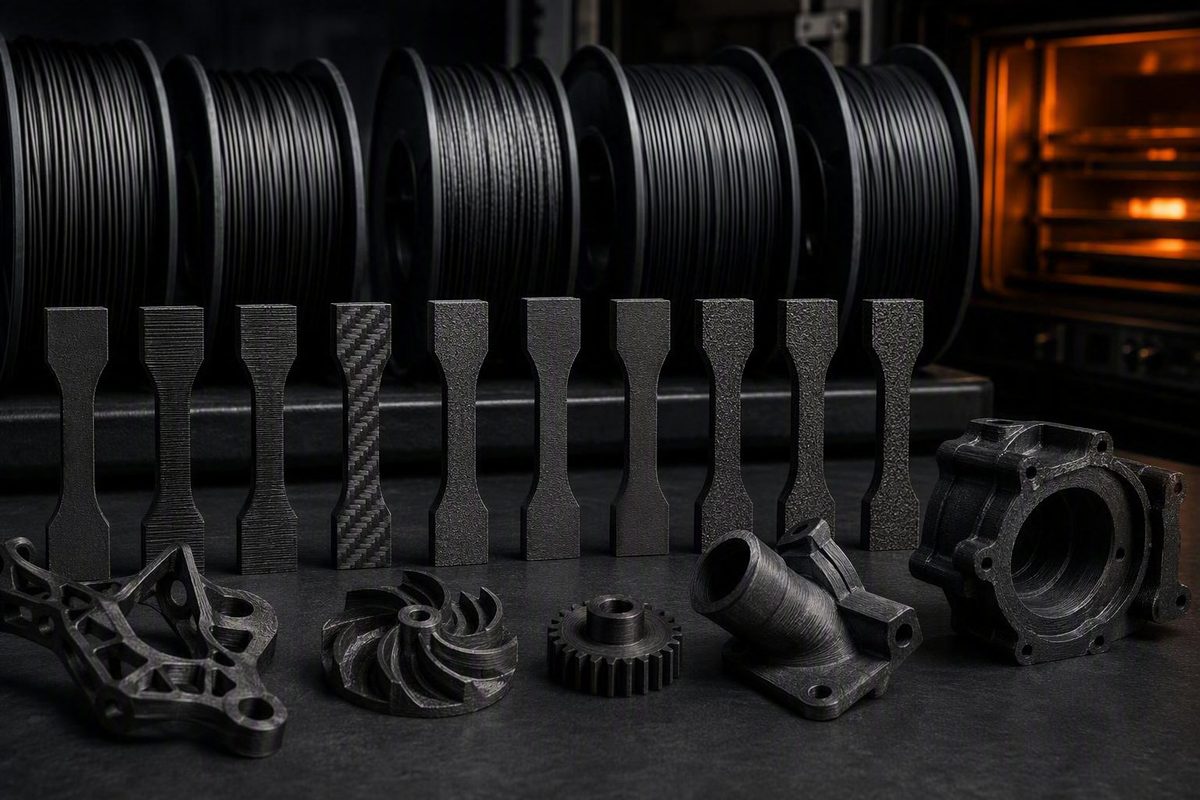
No—not as a general rule. In a 160-specimen comparison, annealing produced little meaningful benefit for the tested PLA-CF and no clear general strength gain for PETG-CF; microscopy reportedly showed that voids and poor chopped-fiber adhesion remained. Specific PETG-CF and recycled-CF ABS formulations have improved in other studies, but annealing can also weaken the Z direction, reduce impact performance, and distort the part (Hackaday’s experiment summary).
Choose your filament, required property, load direction, and tolerance; the tool returns the evidence-based next step.
The result distinguishes documented product processes from material families that require comparative testing. A dash means the accessible evidence did not provide a numerical value.
The summarized PLA-CF test found little meaningful benefit and no improved chopped-fiber adhesion. Compare matched samples before treating a functional part.
Use the controls to highlight relevant rows, or sort the complete evidence table.
| Material / Condition | Reported Strength Change | Z Change | XY Change | Evidence Meaning |
|---|---|---|---|---|
| PLA-CF, summarized 160-specimen test | Little meaningful benefit | Expansion reported; value — | Shrinkage reported; value — | Voids remained; no improved fiber–matrix adhesion observed |
| PETG-CF, summarized 160-specimen test | No clear general gain | Expansion reported; value — | Shrinkage reported; value — | Unfilled PETG responded more favorably; adhesion did not improve |
| PETG-CF, peer-reviewed bending study | Up to 31.8% flexural strength; 61.1% modulus | — | Varied with time and temperature; value — | Useful flexural evidence, not universal tensile or layer data |
| Recycled-CF ABS, 20 wt% fiber | Up to 12.64% tensile; 42.33% flexural | — | — | Maximum gains for the tested formulation and conditions |
| Recycled-CF ABS, 10 wt% fiber | Numerical change unavailable here | — | — | Included in the study, but cited maxima belong to 20 wt% |
| UltiMaker PET CF, maker process | +30% broadly labeled strength; −15% Z tensile | 1.7% maker-reported shrinkage | 0.3% maker-reported shrinkage | Also +10% stiffness and heat resistance from 80°C to 180°C |
| Nylon-CF, product-dependent annealing | Mechanical percentage — | — | — | Some products use annealing to reach intended crystallinity |
| PET-CF17 / PPS-CF10, maker process | Mechanical percentage — | — | — | Maker says annealing is required for full heat resistance |
Sources: the peer-reviewed PETG-CF and recycled-CF ABS studies, Hackaday’s summary of the 160-specimen test, and UltiMaker and Polymaker product guidance cited in the article. Values are maxima or product-specific reports, not universal expectations; — means unavailable.
Carbon Fiber Does Not Guarantee Better Annealing
Here, annealing means heat-treating the finished FDM print—not heating filament on its spool. The part is held at a controlled, material-specific temperature and cooled under controlled conditions.
The relevant materials contain short or chopped carbon fibers in a thermoplastic matrix. The evidence does not extend to continuous-carbon-fiber composites, whose reinforcement architecture and load paths are different.
The polymer matrix controls much of what happens during annealing. Depending on the formulation, heat can increase crystallinity, relieve residual stress, alter contact between deposited roads, change void geometry, or deform the part. Carbon fibers can affect stiffness, shrinkage, thermal expansion, and load transfer, but they do not replace the matrix or automatically repair a poor fiber–polymer interface.
That distinction explains the conflicting results. One PETG-CF formulation can improve under a particular schedule while another fails to gain useful strength. PLA-CF, PETG-CF, ABS-CF, PET-CF, nylon-CF, and PPS-CF are not interchangeable materials, even when every spool is marketed as carbon-fiber filament.
Fiber content, fiber length, sizing, additives, moisture, print orientation, raster layout, void content, temperature, hold time, cooling method, specimen geometry, and test method can all change the outcome. A percentage measured for one formulation and loading direction is not a typical gain for the wider material category.
“Stronger” Must Identify a Property and Direction
Annealing does not change every mechanical property together. Tensile strength, flexural strength, bending stiffness, impact resistance, creep, interlayer strength, and heat resistance describe different behavior.
A higher flexural modulus means the specimen became stiffer in bending. It does not prove an equivalent increase in tensile strength, toughness, impact resistance, or layer adhesion. Greater heat resistance means the part retains its shape or function at a higher temperature; it does not necessarily carry a larger room-temperature load.
Direction matters because FDM parts are anisotropic. A treatment can improve behavior along deposited roads while weakening the bond across layers. That mixed result is not contradictory—it reflects different load paths and failure modes.
UltiMaker’s data for its PET CF illustrate the problem. The company reports 30% greater broadly labeled strength, 10% greater stiffness, and heat resistance increasing from 80°C to 180°C after annealing. It also reports an approximately 15% reduction in Z-axis tensile strength and warns that impact resistance may decline (UltiMaker PET CF annealing guide).
Those figures apply to that named product and process. They cannot be transferred to PETG-CF, another PET-CF formulation, or a nylon-CF part.
The 160-Specimen Test Did Not Repair CF Adhesion
The summarized independent experiment compared PLA, PLA-CF, PETG, and PETG-CF across 160 specimens. It examined tensile behavior, stiffness, failure, dimensional movement, and scanning electron microscope images.
The tested PLA-CF showed little meaningful annealing benefit. PETG-CF did not show a clear general strength improvement, while unfilled PETG responded more favorably. The microscopy reportedly found persistent voids and no improved adhesion at the chopped-fiber–polymer interface.
That result directly challenges the idea that reheating lets the polymer close every gap around a chopped fiber. Annealing may change the bulk matrix or deposited-road geometry without improving load transfer at the fiber surface.
The test also reported planar shrinkage and Z expansion after annealing. Chopped fiber restrained much of that movement, but better dimensional stability did not correspond to better strength.
Complete numerical results for the eight test conditions, uncertainty estimates, filament formulations, print settings, and full heat-treatment procedures were not available in the accessible summary. The result should therefore be read as evidence against assuming a CF benefit, not as proof that every PLA-CF or PETG-CF formulation behaves identically.
Some PETG-CF Formulations Gain Flexural Performance
A 2023 peer-reviewed PETG-CF study found maximum observed increases of 31.8% in bending strength and 61.1% in bending modulus under its best tested conditions. It also reported benefits in hardness, impact behavior, stress relaxation, and creep (peer-reviewed PETG composite study).
Those are substantial results for a bending-dominated component. The lower stress-relaxation and creep-displacement values may also matter for a part carrying a sustained load.
They are not universal PETG-CF gains. The headline values were maxima for particular specimens, processing conditions, and tests. The bending-modulus result describes stiffness, not failure strength, and neither percentage establishes an improvement in Z-axis adhesion.
Dimensions varied with annealing temperature and exposure time. The study found no significant influence from the added fibers on dimensional variation, unlike the 160-specimen experiment in which chopped fiber reportedly restrained movement. Even dimensional behavior is therefore formulation- and process-specific.
The two PETG-CF results should not be averaged into an expected percentage. Their disagreement is the practical finding: PETG-CF can respond favorably, but its name alone does not predict whether annealing will help.
Recycled-CF ABS Improved in Tension and Flexure
A separate peer-reviewed study compared neat ABS with formulations containing 10% and 20% recycled carbon fiber by weight. For the 20 wt% formulation, the maximum reported improvements after annealing were 12.64% in tensile strength and 42.33% in flexural strength (recycled-carbon-fiber ABS study).
The larger flexural gain again shows why “stronger” needs a test name. A bending-dominated part may benefit more than a tension-dominated one.
The researchers attributed the improvements partly to narrower voids and smaller gaps between fibers and polymer. That differs from the persistent interface gaps reported for the tested PLA-CF and PETG-CF specimens. Annealing can improve internal structure in a compatible system, but it does not do so reliably across matrices and fiber treatments.
The ABS results apply to the tested recycled-fiber formulations. A commercial ABS-CF containing different fibers, sizing, additives, or loading cannot be assigned the same percentages without comparative testing.
PLA-CF Has No Reliable General Strength Gain
The available direct comparison gives no basis for promising that annealing makes PLA-CF stronger. Its tested PLA-CF showed little meaningful benefit, and microscopy did not reveal improved adhesion around the chopped fibers.
That does not prove that every PLA-CF product is unaffected. HT-PLA, impact-modified PLA, and proprietary blends can have different matrix behavior. It means the result is unknown unless the exact manufacturer provides relevant data or matched tests establish a gain.
Evidence from unfilled PLA cannot fill that gap. An unfilled material may change crystallinity, tensile behavior, or heat resistance differently from a filled blend. Even a tensile improvement would not by itself demonstrate better layer adhesion or impact resistance.
For a PLA-CF part whose only objective is higher mechanical strength, the defensible default is not to anneal the finished component on assumption. Test coupons first or select a material with documented performance in the required property.
PET-CF, Nylon-CF, and PPS-CF Often Target Heat Resistance
Some semi-crystalline materials are designed around a post-print crystallization step. For those products, annealing may be part of reaching the intended thermal state rather than an optional attempt to raise room-temperature strength.
Polymaker says its nylon materials benefit from annealing to reach their intended crystallinity. It also identifies PET-CF17 and PPS-CF10 as products that require annealing to reach full heat resistance (Polymaker’s material-specific guidance).
The guidance supports annealing those named products according to their instructions. It does not supply a universal tensile, flexural, impact, or Z-axis percentage for nylon-CF, PET-CF, or PPS-CF.
Polymaker gives a general range of 80–100°C for 6–16 hours for its nylon materials while explicitly noting that individual products differ. That range must not be transferred to PLA-CF, PETG-CF, ABS-CF, another brand’s nylon-CF, or an unspecified carbon-fiber blend.
When heat resistance is the actual requirement, a manufacturer-validated annealing process can be justified even without a general strength increase. The finished part still requires dimensional and mechanical checks in its critical load direction.
Distortion Can Erase a Mechanical Gain
Annealing commonly causes directional movement rather than uniform scaling. Reported effects include XY shrinkage, Z expansion, warping, sagging, hole movement, and localized deformation around changes in section thickness.
UltiMaker reports product-specific annealing shrinkage values of 0.3% in XY and 1.7% in Z for its PET CF. It also warns about warping and sagging, recommends avoiding walls thinner than 4 mm, and advises supporting significant bridges or overhangs.
These are instructions for that product, not universal CF-print design rules. A different formulation, geometry, oven, support method, or thermal cycle can move differently.
A single scale-compensation percentage cannot correct bowing, hole ovality, sagging, or asymmetric movement. Tight-tolerance features must be measured independently in X, Y, and Z. Mating faces, holes, boss spacing, bearing seats, thin walls, bridges, and insert locations deserve particular attention.
Distortion is decisive when a component cannot be machined or requalified after treatment. A coupon can post a higher strength while the actual part becomes unusable because its load path, fit, or flatness changed.
The Evidence Supports Three Different Decisions
Follow the manufacturer’s annealing process when the exact product is designed around it, particularly where crystallization or heat resistance is the objective. Verify dimensions and the service-relevant property afterward; a validated thermal process is not a guarantee that every mechanical measure improves.
Run controlled annealed-versus-unannealed tests when direct evidence exists for the same matrix and relevant property. PETG-CF under bending and recycled-CF ABS under tension or flexure are reasonable candidates. The favorable study result is a reason to test, not a percentage to insert into a design calculation.
Avoid annealing the finished part when its critical tolerance cannot accommodate directional movement, its primary load crosses layers, or impact performance is essential and no product-specific evidence covers that mode. PLA-CF and unspecified PETG-CF should remain “do not assume” materials.
A material switch may be more direct when the requirement is outside the favorable evidence. A heat-exposed part may need a matrix designed for post-print crystallization. A layer-critical component may need a different orientation, geometry, or manufacturing process rather than a heat treatment that primarily improves in-plane stiffness.
Load-bearing and safety-critical parts require validation at the finished-part level. None of the cited percentages certifies a final design or establishes a general safety factor.
Matched Tests Must Reproduce the Real Load Path
Begin with the exact manufacturer, product, batch if available, matrix, published fiber loading, and drying history. Use the current instructions for that product rather than a generic carbon-fiber schedule.
Define one primary success criterion and the maximum acceptable losses elsewhere. A useful criterion might be higher flexural strength without excessive hole movement, lower creep without a Z-axis tensile loss, or greater heat resistance while retaining required impact performance.
Print annealed and unannealed specimens from the same material batch with the same orientation, raster direction, layer height, walls, infill, nozzle settings, conditioning, and representative geometric features. One successful coupon cannot reveal process variation; the available evidence does not establish a universal sample count.
Measure defined X, Y, and Z points before treatment. Record the oven set point, actual part-zone temperature if measured, hold time, heating and cooling method, support or restraint, specimen orientation, and visible distortion. “Annealed” by itself is not a reproducible process description.
Test the property and direction that govern the part. A bending requirement needs a relevant flexural test. A layer-critical component needs specimens loaded across layers. Impact, creep, sustained temperature, and thermal cycling cannot be replaced by a room-temperature in-plane tensile result.
Advance to representative parts only after the coupons show a repeatable gain without unacceptable dimensional change. Remeasure every assembly interface after annealing and test the component under a service-relevant load and environment.
The current evidence does not provide a universal temperature, duration, cooling schedule, or expected strength increase for carbon-fiber filament. It supports annealing as a material-specific process that can help selected properties—and as a poor shortcut for unresolved voids, weak fiber adhesion, or the wrong polymer matrix.