
Carbon Fiber Manufacturing: Choose the Process for the Part
Compare carbon fiber manufacturing routes and identify the fiber, resin, layup, cure and inspection controls a finished composite part needs.
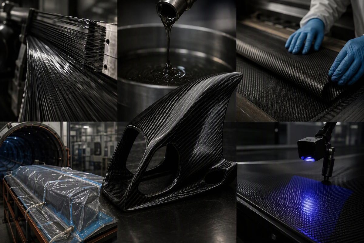
Carbon fiber manufacturing involves two distinct operations: making the carbon filaments and turning those filaments into a composite part. A composite shop normally starts with purchased tow, fabric, prepreg or molding compound—not the polymer precursor used by a fiber producer.
For a finished carbon-fiber-reinforced polymer (CFRP) component, the manufacturing decision is not simply “which carbon fiber?” It is which combination of fiber, resin, ply orientation, tooling and consolidation process will meet the loads, geometry and production quantity. Composites UK’s manufacturing guide identifies finished properties, material costs, tooling, equipment and part quantity as linked process-selection factors.
How the carbon fiber itself is manufactured
Polyacrylonitrile, or PAN, is the precursor for the most common type of carbon fiber. Pitch is another important precursor, with different processing requirements and resulting properties. The PAN route can be summarized as follows:
- Spin and draw the precursor. PAN is dissolved and spun into fine polymer filaments, then washed and stretched. Drawing increases molecular alignment along the filament axis; defects introduced here can affect the eventual carbon fiber.
- Stabilize it in air. Heat converts the PAN into a structure that can retain its shape during subsequent high-temperature processing.
- Carbonize it without oxygen. High-temperature treatment removes non-carbon elements in an inert atmosphere. Toray describes carbonization at 1,200–1,500°C. Further heat treatment at roughly 2,000–3,000°C can develop higher-modulus grades; this is not a required step for every fiber.
- Treat the surface. Surface treatment promotes adhesion between the fiber and the eventual matrix.
- Apply sizing and package the tow. A thin polymer coating improves handling and can improve compatibility with the selected resin system.
The spinning and thermal-conversion mechanisms are explained in the published review Fabrication and Properties of Carbon Fibers; the temperature ranges and distinctions between surface treatment and sizing are given in Toray’s carbon fiber terminology.
The output is reinforcement, not a rigid finished component. Tow can subsequently be woven, braided, assembled into non-crimp fabrics, impregnated with resin or chopped. Weaving is optional: unidirectional tape, wound tow and chopped-fiber compounds are separate manufacturing paths, as Toray’s application guidance shows. For a closer look at the upstream sequence, see how carbon fiber is made.
Choosing a composite-part manufacturing route
The practical distinction between processes is how the reinforcement is positioned, how resin reaches it, and how the assembly is compacted and hardened.
| Route | How it works | Useful starting point for selection |
|---|---|---|
| Wet layup | Liquid resin is applied manually to reinforcement on a mold. | Bespoke or low-volume parts where low equipment investment matters; application and compaction need consistent control. |
| Vacuum infusion | Dry reinforcement is sealed beneath a bag; a pressure difference draws resin through it. | Large shells and panels; fabric permeability and the resin-flow plan are important. |
| Prepreg with oven cure | Reinforcement arrives pre-impregnated; plies are laid up and typically vacuum bagged for heating. | Parts using a resin system specifically suited to vacuum-only processing. |
| Prepreg with autoclave cure | A vacuum-bagged layup is heated under additional external pressure. | Structural parts whose material system and quality requirements call for this consolidation route. |
| Resin transfer molding (RTM) | Resin is injected into dry reinforcement held inside a closed mold. | Repeated shaped parts where investment in matched tooling can be justified. |
| Filament winding | Resin-impregnated tow is wound around a mandrel at selected angles. | Tubes, tanks and pressure-vessel geometries. |
| Pultrusion | Reinforcement is pulled through resin and a heated shaping die. | Long products with a constant cross-section, such as bars and profiles. |
These mechanisms and typical applications are described by Composites UK. The table is a shortlist, not a performance ranking: no process name establishes the strength of a particular part.
Compression molding of carbon-fiber compounds offers another route. Thermoplastic composites generally use heat to melt the matrix and cooling to solidify it rather than the crosslinking cure used by thermoset epoxies. These routes are described in Composites UK’s process guide, with carbon-specific material forms covered by Toray. Those material forms should not be treated as interchangeable with a continuous-fiber laminate merely because each contains carbon.
Layup determines where the reinforcement works
Carbon reinforcement is directional. Unidirectional material delivers its strongest reinforcement along the fibers; a woven fabric provides reinforcement along its yarn directions. Rotating plies changes the laminate response, so ply angles and stacking sequence belong in the manufacturing specification—not just the total thickness. Hexcel’s Prepreg Technology guide explains how reinforcement form and orientation affect mechanical performance.
Straightness also matters. A woven yarn bends over and under neighboring yarns, producing crimp. Hexcel explains that lower crimp improves mechanical performance because straighter fibers carry load more effectively, while greater drapeability helps reinforcement conform to complex molds. Evaluate both characteristics; they are not necessarily opposing properties. Hexcel’s guide, for example, describes satin weave as having good drapeability and low crimp.
The matrix is not simply glue added to hold the checkerboard pattern together. It supports the fibers, transfers loads and maintains their orientation. Its environmental resistance and temperature capability also constrain the part. These matrix functions are described in Hexcel’s guide. Choosing a higher-modulus fiber does not remove the need to select an appropriate resin and layup.
Cure and consolidation are separate controls
For heat-cured thermoset prepreg, temperature and time drive cure; consolidation pressure compacts the layup. Vacuum bagging removes air and allows the pressure outside the bag to act on the laminate. An autoclave adds external pressure while controlling temperature. Other resin systems may cure at ambient temperature, so heating is not a universal requirement for making CFRP.
Vacuum-only consolidation has a pressure difference of up to approximately one atmosphere, or 1 bar. Autoclave processing provides additional pressure and can produce high-fiber-volume, low-void laminates. However, Hexcel also notes that suitable vacuum-bag prepregs can produce near-autoclave-quality components, depending on the material and application. Neither route excuses trapped air, a leaking bag or an unsuitable cure cycle. Source: Hexcel’s processing guide.
For example, HexPly M56 is specifically formulated for vacuum-pressure-only cure. Its 2020 datasheet gives a typical monolithic-part cycle that includes a 60-minute dwell at 110°C, followed by 120 minutes at 180°C, with specified tolerances, ramp rates, vacuum changes and cooling requirements. That is an example of a material-specific process—not a generic carbon-fiber recipe. Use the applicable supplier instructions for the material being processed. Source: Hexcel M56 product datasheet.
Cure temperature is also not the same as allowable service temperature. Select the system using its cured properties and operating environment, then follow its processing instructions.
Quality control must follow the part through production
A glossy surface cannot establish internal laminate quality. A useful manufacturing plan controls:
- Incoming material: fiber grade, reinforcement form, sizing compatibility, resin identity and batch traceability.
- Layup: ply count, angles, sequence, local reinforcement and conformity to the tool.
- Storage and handling: for prepreg, product-specific freezer life, accumulated room-temperature exposure and protection against condensation.
- Processing: bag integrity, air-removal paths, vacuum or pressure, and temperature measured on the tool and part.
- Acceptance: dimensions, surface condition, internal inspection where required, and appropriate coupon or component testing.
Hexcel’s guidance states that prepreg cure time starts when the lagging thermocouple reaches the minimum cure temperature, not merely when the oven display reaches its setpoint. It also describes visual inspection, ultrasound and thermography as different ways to assess defects, and defines prepreg out life as accumulated room-temperature exposure before cure. Source: Prepreg Technology.
For a structural order, specify inspection methods and acceptance limits before production. Ask for property evidence representative of the actual material, layup and process; a filament datasheet alone cannot substantiate completed-part performance.
What to specify before buying equipment or commissioning parts
Start with geometry, loads, allowable deflection, service temperature, exposure, interfaces, tolerances and annual quantity. Then compare process proposals against those requirements.
A quotation should distinguish material cost from engineering, tooling, layup labor, cure capacity, trimming, finishing and inspection. A low-cost mold may suit a prototype but leave too much recurring labor for production; expensive matched tooling needs enough repeat work to justify it. Use the custom carbon fiber parts specification guide to turn those requirements into a supplier brief.
Choose the manufacturing route that can repeatedly deliver the specified part—not the route with the most impressive equipment name.