
A Practical Guide to Carbon Fiber and the Composites Made From It
Filaments become rigid CFRP through a matrix and cure; orientation and manufacturing shape performance, while damage, repair and recycling impose limits.
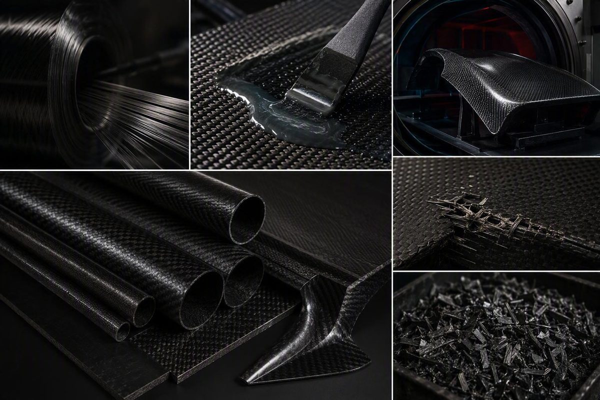
Carbon fiber is often discussed as though it were a single, universally superior material. It is more useful to think of it as one constituent in a designed composite system.
The precursor and fiber grade matter, but they do not determine component performance by themselves. Fiber orientation, reinforcement architecture, resin, cure quality, laminate thickness, geometry, defects, loading direction, service environment, inspection requirements, and cost all affect what the finished part can do.
That distinction explains why a roll of dry carbon cloth is flexible, a cured carbon-fiber panel is rigid, and two visually similar parts can behave very differently.
This guide is an introduction, not a source of design allowables, process specifications, occupational-safety controls, or return-to-service approval. Structural and safety-critical decisions require qualified engineering data, current manufacturer instructions, appropriate inspection, and any applicable standards.
What carbon fiber is—and what it is not
Carbon fibers are fine filaments composed mostly of carbon, commonly around 5–10 micrometers in diameter. Thousands of filaments can be gathered into a bundle called a tow, which may be used directly or converted into fabrics and other reinforcement formats. Carbon fibers are associated with high axial stiffness and tensile strength, chemical resistance, heat tolerance at the fiber level, and low thermal expansion, but those characteristics do not transfer unchanged to every carbon-fiber component. The basic terminology and approximate filament diameter are summarized in this overview of carbon fibers.
A practical way to understand the material is to keep four levels separate:
- Filament: An individual microscopic carbon fiber.
- Reinforcement architecture: The arrangement of filaments and tows, such as unidirectional material, woven fabric, braid, tape, or sleeve.
- Cured laminate: One or more reinforcement layers combined with a matrix and cured.
- Finished component: The complete panel, tube, frame, bracket, shell, or other part, including its geometry, joints, inserts, coatings, and manufacturing condition.
A filament is not a fabric, and a fabric is not a finished part.
Dry carbon-fiber reinforcement generally remains flexible. Woven cloth can fold, fray, and conform to a mold because the individual filaments have not yet been fixed into a rigid structural shape. The reinforcement becomes part of a rigid composite when it is combined with a suitable matrix—commonly a polymer resin—and cured.
The resulting material is commonly called carbon-fiber-reinforced polymer, abbreviated CFRP.
In everyday language, a “carbon-fiber panel,” “carbon frame,” or “carbon monocoque” usually means CFRP rather than bare carbon filaments. The shorthand is convenient, but it can hide the fact that the finished component is a combined system of reinforcement and matrix.
This distinction also explains why the tensile strength or elastic modulus quoted for a raw fiber cannot simply be assigned to woven cloth, a multidirectional laminate, or an entire component. Weaving changes fiber paths. A multidirectional layup intentionally places reinforcement in several directions. Holes, joints, radii, inserts, thickness changes, resin content, cure quality, defects, and loading mode further separate component behavior from a fiber datasheet.
A fiber datasheet can support constituent selection. It is not a certificate for the finished part.
From early carbon filaments to modern high-performance fiber
Carbonized filaments predate modern structural composites. Early electric-lighting work used carbonized cellulose materials, including cotton thread and bamboo-like precursors, because they could function as lamp filaments. Other early carbon fibers were used for purposes such as insulation, filtration, and heat shielding.
Those materials belong to carbon fiber’s history, but they should not be confused with later high-performance structural reinforcement. A material suitable for a lamp, filter, or thermal application does not necessarily have the stiffness, strength, consistency, or processability needed for a load-bearing composite.
A major high-performance milestone came in 1958, when Roger Bacon produced graphite whiskers at Union Carbide. These laboratory filaments had an unusually ordered structure and exceptional reported mechanical properties. They were also extraordinarily expensive: Bacon estimated a production cost of $10 million per pound. The whiskers demonstrated what highly ordered carbon structures could achieve, but their properties and cost were not representative of ordinary commercial laminates then or now. The American Chemical Society’s history of high-performance carbon fibers traces this work and the subsequent development of rayon- and PAN-based fibers.
Rayon played an important part in early commercialization. Researchers developed heat-treatment and hot-stretching methods intended to improve carbon alignment and stiffness, helping move carbon reinforcement from an unusual laboratory material toward commercial fiber.
Polyacrylonitrile, or PAN, subsequently became the principal precursor for modern structural carbon fiber. Laboratory PAN-based fibers appeared in the early 1960s, followed by pilot-scale production and further development in Japan and England. PAN-based routes eventually displaced most rayon-based structural fiber in the market described by the historical evidence.
That history does not establish PAN as categorically best for every requirement. Precursor chemistry and heat treatment produce different carbon structures and property balances.
PAN-derived fibers are generally described as turbostratic: their carbon layers have substantial alignment along the fiber axis without the fully ordered stacking associated with ideal graphite. Suitable pitch-derived fibers, particularly those made from mesophase pitch, can become more graphitic after high-temperature treatment. These pitch-derived routes can be useful when especially high axial stiffness or thermal conductivity is the priority.
Higher modulus is not synonymous with universally better structural performance. Fiber selection must account for the actual property balance, laminate architecture, manufacturing route, load case, and economic constraints. The practical question is not “Which precursor wins?” but “Which fiber system fits this component?”
How carbon fiber is made and turned into a composite part
The production chain begins with a carbon-containing precursor and ends with a component whose behavior depends on every intermediate step.
At a high level, the sequence is:
- Form the precursor into continuous filaments.
- Process the filaments under controlled heat and tension.
- Carbonize them in a controlled atmosphere.
- Apply any required surface treatment and protective sizing.
- Gather the filaments into tow.
- Convert the tow into a reinforcement format.
- Combine the reinforcement with a matrix.
- Consolidate and cure the material into a laminate.
- Trim, inspect, finish, and integrate the laminate into a component.
Carbonization removes much of the non-carbon content. Thermal processing and alignment along the fiber axis contribute to the resulting axial properties.
This is more controlled than simply heating plastic thread. Precursor quality, temperature, atmosphere, tension, and processing history affect the fiber that emerges. PAN-derived fiber generally develops a turbostratic structure, while suitable pitch-derived fiber can become more graphitic after sufficiently high-temperature treatment. These are descriptions of fiber structure, not direct predictions of how a woven or multidirectional component will perform.
After production, the filaments are collected into tow. Tow can be wound onto spools or converted into formats including:
- Unidirectional reinforcement
- Woven cloth
- Narrow tape
- Braided sleeves
- Tubular braids
- Multiaxial or non-crimp reinforcement
- Pre-impregnated reinforcement, commonly called prepreg
- Chopped or discontinuous reinforcement
The chosen form affects how easily the reinforcement can be cut, placed, draped, impregnated, compacted, and aligned with the intended load paths.
The reinforcement must then be combined with a matrix. Polymer matrices, including epoxy systems, are common, but resins are not automatically interchangeable.
Possible fabrication routes include hand layup, wet layup with vacuum bagging, resin infusion, matched-tool or compression molding, prepreg layup, presses, and autoclave processing. These are process options, not automatic quality labels. An autoclave cannot compensate for an unsuitable laminate design, while a vacuum bag does not prove that a part is free of defects.
The manufacturing route must fit the material form, geometry, production volume, dimensional requirements, surface expectations, and acceptable defect level.
For a shorter companion overview, see this internal guide to how carbon fiber is made from precursor to finished part.
The complete production chain also explains why carbon-fiber parts can be expensive. Cost is not simply the price of carbon or a square meter of cloth. Depending on the application, it may include:
- Controlled precursor production
- High-temperature conversion
- Tow handling and reinforcement conversion
- Resin or prepreg
- Storage appropriate to the selected material
- Tooling
- Release materials and other consumables
- Cutting and ply preparation
- Skilled layup labor
- Infusion, bagging, pressing, or autoclave equipment
- Cure time and energy
- Trimming and dust management
- Inspection and testing
- Finishing and coating
- Scrap and rejected parts
A credible cost comparison must therefore define the material system, component, process, production volume, quality requirements, and inspection burden. There is no universal carbon-fiber price multiplier that applies equally to prototypes, cosmetic panels, aircraft structures, pressure vessels, and high-volume molded parts.
Why carbon-fiber composites perform well—and why results vary
Carbon fiber is useful because its filaments can provide high axial stiffness and tensile strength at relatively low mass. Other fiber-level characteristics include low thermal expansion, chemical resistance, and tolerance of temperatures that would be unsuitable for many polymer materials. These general properties and their application dependence are summarized in the same carbon-fiber technical overview.
The key word is axial. Carbon reinforcement is anisotropic: its response depends on direction.
Imagine a bundle of straight fibers running from one end of a strip to the other. A tensile load parallel to those fibers can engage them efficiently. Turn the load across the fibers, and behavior depends much more on the matrix, interfaces, transverse reinforcement, and laminate design. A component can therefore be extremely stiff in one direction and comparatively compliant or vulnerable in another.
This directional behavior is not necessarily a disadvantage. It is one of composite design’s main opportunities. Reinforcement can be allocated along intended load paths instead of providing the same properties in every direction. That advantage depends on understanding the loads and maintaining the required fiber orientations during manufacture.
Unidirectional reinforcement concentrates most continuous fibers along selected directions.
Woven cloth places fibers in two principal directions and can be stable and convenient during handling. Weave pattern also affects drape, stability, surface texture, and how the reinforcement behaves during fabrication.
Two parts made with nominally the same carbon fiber may differ because of:
- Precursor and fiber grade
- Filament and tow characteristics
- Fiber orientation
- Woven, braided, stitched, or unidirectional architecture
- Fiber fraction and resin content
- Matrix selection
- Cure conditions
- Voids, wrinkles, poor wet-out, contamination, or displaced reinforcement
- Ply sequence and laminate thickness
- Local reinforcement and thickness transitions
- Geometry, joints, fasteners, and inserts
- Loading direction and rate
- Impact and fatigue history
- Service temperature and chemical exposure
This is why isolated headline numbers can mislead. A filament tensile result does not describe a woven multidirectional panel. A flat coupon does not automatically represent a curved tube with a bonded insert. A tensile test does not establish compressive, shear, bearing, fatigue, or impact performance.
Temperature claims require the same discipline. Carbon filaments may tolerate high temperatures under appropriate conditions, but that does not establish the operating limit of a polymer-matrix composite. The matrix can lose useful properties or degrade at a substantially different temperature. The allowable condition must therefore be established for the complete material system, exposure, and load case.
Other limitations include comparatively high material and processing costs, directional behavior, demanding quality control, and failure modes that may be brittle or sudden. Impact can cause matrix cracking, fiber damage, or separation between layers without producing the obvious dent expected in a metal part. Damage may remain hidden beneath paint or apparently intact surface layers.
Recovery may produce shorter reinforcement or material suited to a different application.
These limitations do not make carbon fiber a poor material. They make it application-specific. Claims that it is a fixed multiple “stronger than steel” or “stronger than aluminum” omit the information required for a valid comparison: material grades, density basis, fiber direction, laminate schedule, geometry, loading mode, failure criterion, and test method.
Tow counts, weaves, weights, and reinforcement formats
Carbon-fiber product descriptions often compress several different specifications into one line. Understanding each term prevents a purchasing or cosmetic label from being mistaken for a structural property.
Tow count
- 1K: about 1,000 filaments
- 3K: about 3,000 filaments
- 6K: about 6,000 filaments
- 12K: about 12,000 filaments
- 24K: about 24,000 filaments
Commercial reinforcement ranges use these tow designations across fabrics, tapes, braids, sleeves, and other material forms, as illustrated by this carbon-fiber reinforcement catalog.
Tow count does not independently define strength, modulus, quality, or suitability. A 12K fabric is not inherently four times as strong as a 3K fabric.
Unidirectional versus woven reinforcement
Unidirectional material places most of its continuous reinforcement along one axis. It is useful when load paths are known and fibers can be allocated deliberately—for example, along the span of a bending member or around a pressure-loaded cylinder.
Woven cloth interlaces tows in two principal directions. It provides bidirectional reinforcement in a single ply and may remain more stable while being cut and positioned. Its suitability for a particular contour depends on the weave, tow size, fabric weight, and geometry.
Neither form is universally superior. A laminate may combine unidirectional plies for primary loads with woven or off-axis plies for other required directions, handling, or surface purposes.
Plain, twill, and satin weaves
This tends to create a stable fabric but also creates frequent crimp and may limit conformity over some complex surfaces.
A twill weave, such as 2×2 twill, uses a staggered interlacing pattern that produces the familiar diagonal carbon-fiber appearance. Twills offer a different balance of drape, stability, handling, and surface appearance.
The reduced interlacing frequency can change conformity and surface smoothness, although the dry material may also be easier to distort during handling.
These terms describe architecture, not a quality ranking. Geometry, load paths, process, and handling requirements determine which tradeoff is useful.
Areal weight and thickness
A heavier fabric adds fiber mass and builds laminate thickness more quickly, while a lighter fabric may be more practical for thin skins, small features, surface plies, or gradual thickness changes.
Areal weight is not cured thickness.
Retail catalogs illustrate the available variety rather than establishing design rules. One woven-cloth range, for example, spans plain, 2×2 twill, 4×4 twill, and 5-harness satin products in several tow sizes, widths, areal weights, and nominal or consolidated thicknesses. The Easy Composites woven-cloth catalog demonstrates that commercial range, but its application descriptions remain seller guidance rather than independent engineering validation.
A bounded selection process should consider:
- Loads and failure consequences. Identify relevant tension, compression, bending, shear, torsion, bearing, fatigue, and impact demands.
- Required fiber directions. Choose reinforcement orientations before choosing a visible weave pattern.
- Geometry. Consider radii, corners, compound curvature, thickness transitions, cutouts, and inserts.
- Manufacturing process. Match reinforcement stability and formability to the selected process.
- Desired thickness. Determine the required laminate rather than assuming that fabric weight alone defines it.
- Surface finish. Decide whether the outer ply is structural, cosmetic, or both.
- Inspection needs. Consider whether the finished geometry can be inspected to the required level.
- Production volume and budget. Include labor, scrap, tooling, cure, finishing, and quality assurance.
- Engineering data. Use qualified material data and a validated laminate design for structural parts.
An attractive twill surface proves only that a twill pattern is visible. It does not prove that the underlying laminate has the required orientations, thickness, consolidation, or cure quality.
Where carbon fiber earns its place—and where alternatives may be better
Carbon-fiber composites are used in aerospace, automotive and motorsport applications, sporting goods, civil engineering, military equipment, marine products, and other structures where reducing mass or tailoring stiffness has significant value.
Examples include aircraft components, race-car structures, aerodynamic parts, automotive panels, bicycle and racket structures, marine components, and externally applied civil reinforcement. These examples show where carbon fiber can be useful; they do not mean every component in those sectors should use it.
Carbon fiber is most compelling when one or more of the following benefits have enough economic or operational value to offset added material, processing, inspection, and repair costs:
- Reduced mass
- Increased stiffness without a proportional increase in mass
- Reinforcement tailored to known load paths
- Low thermal expansion
- Integrated or aerodynamically complex shapes
- Avoidance of ordinary metal-like corrosion in the composite material itself
- Packaging constraints that favor thin, stiff structures
Those advantages must be evaluated at assembly level. Mixed-material components, joints, fasteners, inserts, coatings, and the service environment require application-specific engineering review; selecting a carbon composite does not by itself resolve every durability or compatibility concern.
Carbon fiber versus aluminum
The useful question is not “Which material is stronger?” It is “Which material system best satisfies this component’s requirements over its lifecycle?”
Carbon composites may offer mass-efficient stiffness, tailored reinforcement directions, low thermal expansion, and opportunities to integrate some shapes. Aluminum offers established routes for extrusion, casting, machining, forming, and welding. It is also widely associated with economical volume production and mature recycling routes, although the suitability and economics of any route depend on the alloy, product form, component, and production context. A commercial comparison of carbon fiber and aluminum illustrates these commonly cited distinctions but does not provide a universal engineering ranking.
A valid comparison should specify:
- Carbon-fiber grade, architecture, laminate, and resin
- Fiber directions and laminate thickness
- Aluminum alloy and temper
- Component geometry
- Loading mode and allowable deformation
- Impact and fatigue requirements
- Service temperature and environment
- Production quantity
- Tooling and cycle-time assumptions
- Joining and assembly methods
- Inspection and quality requirements
- Repair or replacement strategy
- End-of-life route
- Test standards and design allowables
Aluminum may be the better choice for a machined prototype, an extrusion-led design, a welded structure, or a volume-produced part where cycle time and established recycling infrastructure dominate. Carbon fiber may earn its place where mass reduction materially changes payload, energy use, handling, packaging, or competitive performance.
Fiberglass, aramid, steel, and hybrid constructions may also be appropriate. Fiberglass can provide a more accessible composite route in some applications. Steel remains effective for many stiff, durable, economical structures. Hybrid systems can place different materials where each is useful. The available evidence does not support a universal performance ranking among these alternatives.
The decision should be made at component level, not from isolated tensile values or marketing superlatives.
Fabrication quality, vacuum bagging, and safe handling
Selecting an excellent fiber cannot compensate for poor fabrication. A laminate can underperform because of unsuitable constituent selection, misplaced fibers, wrinkles, trapped air, incomplete wet-out, excessive or inadequate resin, contamination, an unsuitable cure, or uncontrolled workmanship.
Fiber placement is particularly important. If a nominally axial ply wanders, wrinkles, or shifts during processing, it no longer follows the intended load path. Resin content also must be controlled: dry reinforcement must be adequately incorporated into the matrix, but simply adding more resin does not guarantee better structural performance.
Vacuum bagging is one method used to compact a wet laminate and manage trapped air or displaced resin. It is a process technique, not proof that the finished part is defect-free.
In one individual bicycle-repair demonstration, the stack above the prepared component was:
- Carbon reinforcement
- Peel ply
- Perforated release film
- Breather material
- A sealed vacuum bag
The tutorial also describes ventilation, gloves, and respiratory protection selected for resin vapor and sanding dust, while specifically noting that a paper dust mask is not presented as protection against resin gases. These details come from a user-authored repair demonstration, not a validated general fabrication or repair specification.
The exact materials and arrangement must suit the resin system, process, and part.
A bagged laminate can still contain defects. Leaks, blocked vacuum paths, incomplete wet-out, excessive resin removal, bridging, reinforcement movement, contamination, and an unsuitable cure remain possible. Vacuum level alone does not certify laminate quality.
Mixing ratio, working time, cure duration, cure temperature, and any additional cure requirements are specific to the chosen resin. They should come from the current technical documentation for that system, not from an unrelated video or repair account.
Basic workshop precautions include:
- Use ventilation appropriate to the products and process.
- Prevent skin contact with uncured resin through suitable gloves and work practices.
- Select respiratory protection for the actual vapor or dust hazard.
- Manage dust generated by sanding and trimming.
- Keep contaminated materials away from clean work areas.
- Follow current instructions for resins, solvents, coatings, heaters, pumps, and cutting equipment.
This list is introductory, not a complete occupational-safety program. The available sources do not establish comprehensive controls for sensitization, conductive dust, electrical hazards, extraction systems, fire, confined spaces, or waste disposal. Fabricators should consult current safety data sheets, product instructions, equipment manuals, and applicable workplace requirements before beginning work.
Damage, inspection, repair, and end-of-life limits
Carbon-fiber damage is not always obvious. After an impact, visible warning signs may include:
- Cracks or fractures
- Punctures
- Deep gouges
- Cloudy or whitish areas
- Bulges or changes in contour
- Soft spots
- Exposed, cut, or frayed fibers
- Separation around joints or inserts
The absence of these signs does not establish that a component is sound. Damage or separation between layers may exist beneath an apparently intact surface, and paint or clearcoat may conceal changes in the laminate.
Visual inspection is a useful preliminary screen. Cleaning the surface, using good lighting, and comparing the suspect area with an undamaged region may reveal changes.
A comparative tap test is also described in commercial repair guidance: a dull or hollow response relative to a known-good area may identify a suspect region. The same guidance mentions ultrasound and thermography as professional inspection options and outlines a high-level repair sequence. These methods and steps are summarized in a commercial overview of carbon-fiber damage and repair, which should not be treated as a repair standard or return-to-service authority.
A tap response is an indication, not certification. A sharp response does not prove structural safety, and no single inspection method should be assumed to detect every relevant flaw.
If a safety-critical component is damaged or suspected of being damaged, the cautious course is to stop using it and consult the manufacturer or a qualified composite-inspection or repair professional. Appearance, sound, or a generalized patch procedure is not enough to approve a critical component for continued service.
What a professional repair involves
A structural composite repair is a laminate-design, process-control, and inspection task. At a non-prescriptive level, professional evaluation may involve:
- Reviewing the component, service demands, and manufacturer restrictions
- Mapping visible and suspected hidden damage
- Defining the removal boundary
- Removing compromised material without unnecessarily extending the damage
- Preparing the specified repair geometry and bonding surface
- Installing replacement reinforcement in appropriate orientations
- Compacting and curing the repair under controlled conditions
- Inspecting the completed work
- Restoring required protective and cosmetic finishes
- Determining whether the component can return to service
This sequence is not a universal repair instruction. The required method depends on the original laminate, geometry, loads, resin system, access, damage type, inspection findings, and manufacturer requirements.
Matching the visible weave is not enough. A repair must address the actual load path, which may include axial, transverse, off-axis, hoop, shear, or local reinforcement that cannot be identified from the surface appearance.
Repairability depends on damage location and extent, laminate construction, access, nearby inserts, manufacturer guidance, warranty implications, inspection results, economics, and consequences of failure. Widespread delamination and damage around metal inserts are examples identified in commercial guidance as potentially difficult, uneconomical, or unsuitable to repair.
A lightly loaded noncritical cover presents a different decision from an aircraft fitting, bicycle fork, pressure vessel, lifting device, suspension component, or primary motorsport structure. Where failure could cause injury or major loss, uncertainty itself can justify engineering evaluation or replacement.
DIY bicycle repairs illustrate why anecdotal evidence must be treated cautiously. One first-person account describes sanding a cracked top tube, applying two external carbon patches, compressing them with heat-shrink tape, and allowing the epoxy to cure. The author later reported a clear coin-tap response and several successful rides. That personal bicycle-repair account documents what one person attempted; it provides no controlled strength, fatigue, internal-inspection, or long-term safety validation.
A patch can look neat and survive initial use without demonstrating that the original load capacity or fatigue life has been restored. Appearance, coin tapping, and a few successful load cycles are not substitutes for validated repair data and appropriate inspection.
End of life
Cured carbon-fiber composites present a difficult end-of-life problem. Thermoset-matrix components generally cannot be melted and returned to their original continuous-fiber form. They may instead be chopped or processed so that shorter carbon reinforcement can enter molded materials, fillers, or other secondary applications.
That is recovery for a different material form, not automatic restoration of virgin continuous-fiber performance. Other recovery processes may also change fiber length, surface condition, or suitability for a new application.
The available evidence does not establish consistent retained properties, universal environmental benefit, or broad commercial scalability for carbon-composite recycling. Even commercial comparisons that describe recycling as a disadvantage relative to aluminum acknowledge that carbon-fiber recovery remains challenging.
Any sustainability claim therefore needs a defined process and lifecycle boundary. Relevant questions include how the material is collected and transported, how much processing is required, where the recovered material is used, how long both products remain in service, and what realistic alternative is being compared.
Lifecycle planning should begin before the part is made. Material efficiency, durable design, inspection access, repair strategy, long service life, and a credible end-of-life route may matter as much as reducing initial mass.
Frequently asked questions
Is carbon fiber stronger than steel or aluminum?
Not as a universal statement. Carbon fibers can have high axial tensile properties for their mass, but a carbon-fiber component is anisotropic and depends on fiber grade, orientation, resin, cure, defects, geometry, and loading mode. Steel and aluminum also include many grades, tempers, forms, and processing histories.
A meaningful comparison must match specified materials in the same component function and loading condition. It must also define whether “stronger” means tensile strength, compressive strength, stiffness, impact performance, fatigue resistance, bearing strength, or performance per unit mass.
What do 1K, 3K, 6K, 12K, and 24K carbon fiber mean?
They indicate the approximate number of filaments in a tow. A 3K tow contains roughly 3,000 filaments, while a 12K tow contains roughly 12,000.
Tow count affects handling, coverage, appearance, feature size, and thickness-building rate. It does not by itself specify fiber grade, strength, modulus, fabric weight, cured thickness, resin content, or finished-part quality.
What is the difference between carbon fiber and CFRP?
Carbon fiber refers to the fine carbon filaments and, informally, reinforcement made from them. CFRP means carbon-fiber-reinforced polymer: carbon reinforcement embedded in and bonded by a polymer matrix.
Dry carbon cloth is flexible reinforcement. Once combined with a compatible matrix, consolidated, and cured, it becomes a rigid laminate. Most panels, frames, tubes, and shells casually called “carbon fiber” are CFRP components.
Can cracked carbon fiber be repaired safely?
Sometimes, but repairability cannot be determined from the word “crack” alone. It depends on the damage location and extent, laminate construction, load path, access, inserts, manufacturer guidance, inspection findings, cure capability, economics, and consequences of failure.
Visual inspection and comparative tap testing can identify suspect areas but cannot certify safety. Stop using a suspect safety-critical component and obtain manufacturer or qualified professional guidance. A cosmetic patch, clear tap sound, or short period of successful use does not validate static strength, fatigue life, or long-term safety.
Can carbon-fiber composites be recycled?
Some cured composites can be chopped or otherwise processed for short-fiber reuse, and other recovery methods may attempt to separate fibers from the matrix.
The recovered material does not automatically retain the continuous length, orientation, interface, or properties of the original reinforcement. Results depend on the recovery process and the new application. The evidence does not support a blanket claim that carbon-fiber recycling is performance-neutral, broadly scalable, or environmentally superior in every case.
Carbon fiber is best selected through a sequence rather than a blanket endorsement:
- Distinguish the fiber from the finished composite.
- Define the loads, environment, required life, and consequences of failure.
- Select reinforcement directions and architecture around those requirements.
- Match the matrix and manufacturing process to the component.
- Control placement, consolidation, cure, and defects.
- Plan inspection, repair, cost, and end of life.
- Obtain qualified engineering and manufacturer guidance wherever structural or safety-critical uncertainty remains.
Carbon fiber can deliver exceptional mass-efficient performance, but only when the complete composite system is designed, manufactured, inspected, and maintained for the application.