
How to Source a Carbon-Fiber Tube With a Built-In Curve
Treat it as a custom component, then specify geometry, loads, interfaces, quality and quantity before validating supplier claims.
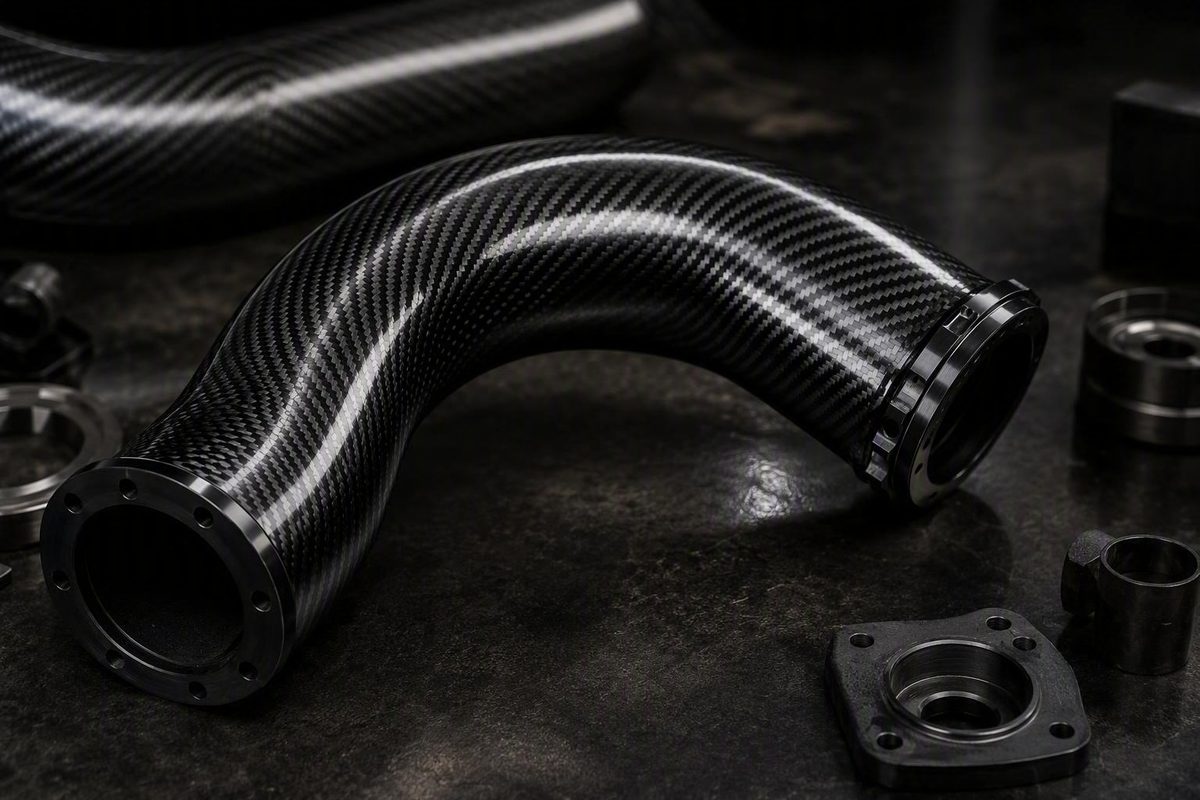
Do not treat curved carbon-fiber tubing as a confirmed catalog product merely because a supplier sells straight tubing or advertises custom fabrication. DragonPlate’s public tubing page does not list a curved-tube category, and its custom-fabrication link does not establish that a particular centerline, laminate, tolerance, quantity, or load requirement can be produced. Treat the tube as a controlled custom component until a fabricator confirms the design in writing and proposes suitable acceptance criteria.
Availability verdict: treat curved tubing as an unverified custom requirement
DragonPlate lists round, square, rectangular, hexagonal, tapered, telescoping, large, and symmetrical-airfoil tubing. It also lists roll-wrapped, braided, and pultruded products, plus tube splices and connector systems, but does not explicitly identify tubing manufactured with initial curvature (DragonPlate carbon-fiber tubing catalog).
That finding is limited to the named supplier page; it is not a market-wide determination that curved carbon-fiber tubes are unavailable. It does mean that buyers cannot use this catalog as proof of either a standard curved product or a demonstrated curved-tube manufacturing capability.
A general custom-fabrication offer is an invitation to submit a requirement. It does not confirm that the supplier can make a continuous curved tube with the requested:
- Centerline radius, sweep, or three-dimensional path
- Cross-section and wall thickness
- Laminate construction or reinforcement continuity
- Ovality, profile, and interface tolerances
- Prototype and production quantities
- Inspection, traceability, or testing requirements
- Price or delivery schedule
The DragonPlate page publishes no curved-part figures for bend radius, dimensions, cost, minimum quantity, lead time, or inspection capability. Obtain part-specific confirmation against a controlled drawing or CAD model before considering the design sourceable.
Define what “curved tubing” means before contacting suppliers
That is not the same engineering case as an initially straight tube that deflects temporarily under an applied bending moment.
Classify the geometry before preparing an RFQ:
Do not assume that cured straight carbon-fiber tubing can be reshaped using conventional metal-tube bending practices. Instead, require the prospective fabricator to identify whether it proposes:
- One continuous component manufactured to its final curvature
- An assembly made from molded or straight sections
- Another documented construction method
The supplier should also disclose the proposed method’s relevant geometry and process limits.
Use this geometry worksheet:
- CAD control: File format, drawing number, revision, units, and precedence between the model and drawing
- Centerline: Radius and curve angle, or a controlled CAD path for variable curvature
- Tangents: Straight lengths before, between, and after curved regions
- Cross-section: Circular, oval, square, rectangular, or another defined profile
- Dimensions: Outside dimensions, critical inside dimensions, and nominal wall thickness
- Shape control: Permitted ovality, flatness, twist, wall-thickness variation, and cross-sectional rotation
- Interfaces: Insert locations, holes, bonded ends, connector zones, trim planes, and keep-out areas
- Datums: Datum reference frame and accessible inspection points
- Tolerances: Profile, position, angular, linear, and interface tolerances
Identify which surfaces and interfaces govern assembly, where deviation affects function, and how the finished geometry will be measured.
Compare a one-piece curve with a joined straight-tube assembly
If a continuous curved component cannot be confirmed, compare it with a segmented assembly or a redesign based on standard straight profiles. The available evidence does not establish that any option is inherently stronger, lighter, cheaper, or more reliable.
| Decision factor | One-piece custom curve | Straight sections with splices or connectors | Redesign using straight profiles |
|---|---|---|---|
| Geometry fidelity | Can the proposed process hold the required path and profile? | Can segment and joint geometry approximate the path within tolerance? | Can the function accept a changed structural path? |
| Laminate continuity | How is reinforcement controlled through the curve? | Where is continuity interrupted, and how are loads transferred? | What continuity is required within each member and node? |
| Number of joints | Which attachments or end fittings remain? | How many splices, inserts, bonds, or fasteners are required? | How many nodes and brackets does the redesign introduce? |
| Tooling requirement | What forming, cure, trim, and inspection tooling is required? | What custom joint or assembly tooling is required? | Which tools remain necessary after changing the architecture? |
| Replaceability | Must the entire component be replaced after damage? | Can individual segments or connectors be replaced? | What is the replacement unit in the redesigned assembly? |
| Inspection access | Can the curved region and interfaces be inspected? | Can every joint be inspected during production and service? | Are all critical members and nodes accessible? |
| Interface complexity | How are end fittings and attachments qualified? | How is each splice, bond, insert, or fastener controlled? | How are loads transferred through nodes and brackets? |
| Qualification burden | What evidence validates the curved-part process and performance? | What evidence validates tubes, joints, and assembly variation? | What evidence validates the revised load path and interfaces? |
A supplier’s listing of splices and connector systems makes segmented construction a category worth investigating, but it does not make a joined assembly structurally equivalent to a continuous tube.
Each joint creates a separate load-transfer and inspection question. Evaluate local stiffness changes, stresses, fatigue requirements, dimensional stack-up, environmental exposure, and the acceptance of bonds or fasteners. Ask specifically whether connectors, inserts, bonded joints, or mechanical fasteners would fall within or immediately beside a highly loaded curved region.
Account for ovalization and the limits of straight-tube evidence
The resulting reduction in moment of inertia can increase deformation and contribute to nonlinear collapse known as Brazier instability.
A 1992 NASA technical memorandum discusses this mechanism for moderate-wall-thickness laminated composite cylindrical tubes. Its analysis concerns initially straight, long, unpressurized tubes under end moments, not tubes manufactured with initial curvature (NASA, “Collapse of Composite Tubes Under End Moments”).
The model also relies on restrictive assumptions, including:
- Specially orthotropic material behavior
- Balanced and symmetric laminates
- Negligible bending–twisting coupling
- Uniform longitudinal bending effects
- Identical cross-sectional deformation along the tube
- Negligible circumferential membrane strain
- Negligible local shell bending
Use the memorandum as a reason to investigate ovalization and nonlinear bending behavior where relevant. Do not derive permissible bend radii, allowable loads, curved-tube laminate schedules, or design values from it.
Those conditions must be addressed according to the actual geometry, laminate, interfaces, service environment, and consequences of failure.
Send suppliers a complete curved-tube RFQ
A complete RFQ makes supplier responses easier to compare and reduces the risk of receiving a price for a materially different component.
Part identification and geometry
- [ ] Part name, drawing number, CAD file, units, and revision
- [ ] Centerline path and controlled coordinate system
- [ ] Bend angle and centerline radius, where applicable
- [ ] Cross-sectional shape and outside dimensions
- [ ] Critical inside dimensions
- [ ] Nominal wall thickness and permitted variation
- [ ] Straight tangent lengths
- [ ] Datum scheme and inspection locations
- [ ] Trim planes, holes, inserts, connectors, and attachment interfaces
- [ ] Dimensional, profile, angular, and ovality tolerances
Loads and service conditions
- [ ] Axial, bending, torsional, and pressure requirements where applicable
- [ ] Impact and fatigue requirements where applicable
- [ ] Load directions, combinations, and boundary conditions
- [ ] Attachment and support assumptions
- [ ] Safety factors specified by the responsible engineer
- [ ] Operating and storage temperature ranges
- [ ] Moisture, chemical, ultraviolet, abrasion, and fire exposure
- [ ] Consequences of failure and critical functional requirements
Construction
- [ ] Required fiber, laminate, or mechanical characteristics already established by the design
- [ ] Permitted supplier alternatives and approval process
- [ ] Required reinforcement continuity through the curve
- [ ] Resin-system requirements
- [ ] Inserts, connector zones, bonded interfaces, and mechanical fasteners
- [ ] Surface finish and cosmetic requirements
- [ ] Paint, coating, or ultraviolet-protection requirements
- [ ] Areas where machining, joints, ply changes, or local reinforcement are prohibited
Commercial requirements
- [ ] Prototype quantity and anticipated production quantity
- [ ] Minimum order quantity
- [ ] Tooling ownership, storage, maintenance, and replacement terms
- [ ] Nonrecurring engineering and tooling charges
- [ ] Recurring unit price by quantity
- [ ] Prototype and production schedules
- [ ] Packaging, labeling, storage, and shipping requirements
Quality and acceptance
- [ ] Material and batch traceability
- [ ] Manufacturing and cure-process records
- [ ] First-article and production dimensional reports
- [ ] Defined allowable defects and repair restrictions
- [ ] Available nondestructive inspection options
- [ ] Proof, qualification, or lot-acceptance testing requirements
- [ ] Acceptance criteria and required documentation
- [ ] Control and disposition of nonconforming parts
Require each bidder to name the actual forming or assembly process, explain how reinforcement and dimensions are controlled through the curve, and disclose applicable geometry limits. The response should distinguish established capability from work that would require development or trials.
Evaluate the response before committing to tooling or production
Separate three levels of evidence:
- Catalog-confirmed product: A documented standard item with a defined specification.
- Supplier-claimed custom capability: A statement that the requested component can be attempted or produced.
- Validated part performance: Evidence that the actual design, manufacturing process, and finished component satisfy the agreed requirements.
Rate every response as confirmed, conditional, unsupported, or unacceptable. “Conditional” should identify the trial, analysis, tooling, inspection, or approval needed to resolve the condition.
| Review area | Evidence to request | Warning sign |
|---|---|---|
| Process description | Named forming or assembly method and process controls | Generic custom-fabrication language |
| Geometry capability | Relevant demonstrated geometry or a development plan | No basis for the proposed path or section |
| Laminate control | Reinforcement placement and control through the curve | Continuity and local variation unaddressed |
| Dimensions and defects | Measurable tolerances, inspection method, and defect criteria | Ovality, wall variation, or defects undefined |
| Inspection and traceability | Records, reports, material identity, and inspection options | “Quality” promised without deliverables |
| Prototype and testing | Staged prototype plan tied to acceptance criteria | Immediate move to production tooling |
| Tooling | Scope, ownership, life, storage, and replacement terms | Tooling responsibilities left undefined |
| Quantity and price | Prototype and production quantities; recurring and nonrecurring charges | Unqualified budget price |
| Schedule | Tooling, prototype, approval, and production milestones | Lead time without assumptions or milestones |
DragonPlate displays an ISO 9001:2015 certification on its supplier page, but that listing is evidence of a stated quality-management certification—not proof of curved-tube capability or performance for a particular component (DragonPlate).
For a safety-critical application, the responsible engineering team should define the necessary analysis, prototype evaluation, dimensional inspection, and other acceptance activities.
Source curved carbon-fiber tubing as a defined custom component. Give prospective fabricators controlled geometry, loads, interfaces, quality requirements, and quantities; require a documented process and stated limitations; and validate the resulting component before authorizing production.