
How to Prove Pipe or Conduit Clearance Without Mistaking the Test for a Full Inspection
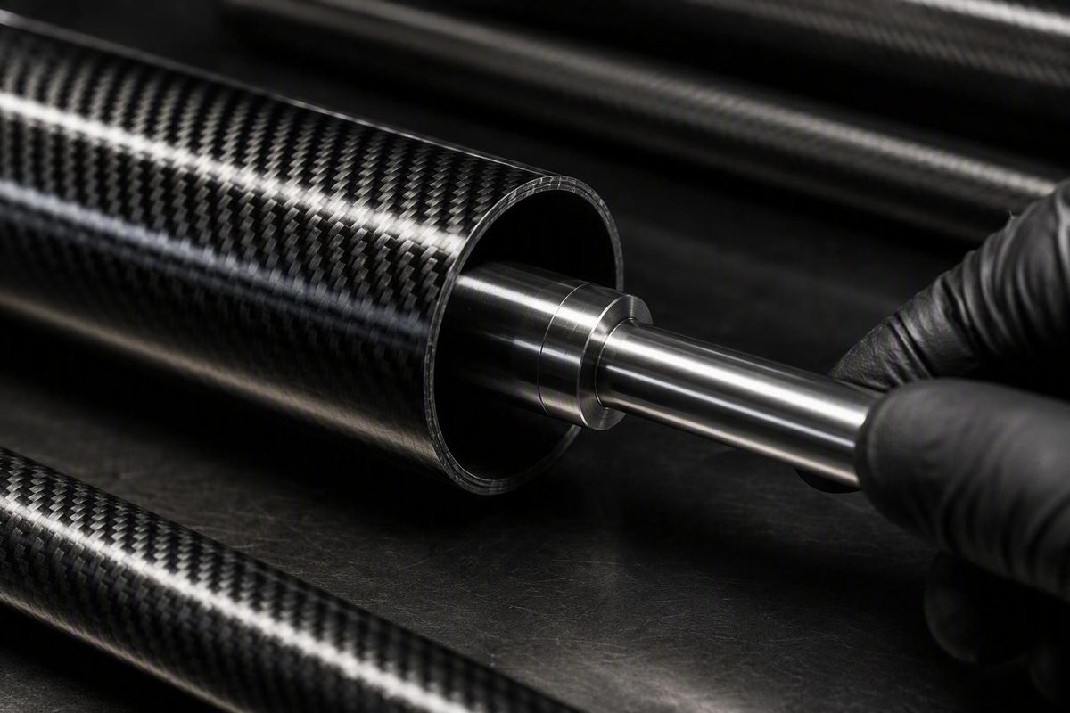
A mandrel test is a physical passage test. A gauge of specified dimensions is pushed or, more commonly, pulled through a pipe or conduit to determine whether the required internal clearance remains available.
The purpose differs by application. In flexible sewer, storm-sewer, and culvert work, the test usually screens for excessive deflection or loss of roundness after installation. In electrical and telecommunications conduit work, it usually proves that a pathway is sufficiently open for cable, wire, innerduct, or subduct installation.
In either case, the test is only as valid as the requirement behind it. The current contract documents or authority specification must establish the mandrel dimensions, diameter basis, acceptance threshold, timing, pull method, sampling, witnessing, verification, and remedy. A catalog gauge labeled “5%” or “7.5%” does not create a project acceptance criterion.
The central interpretation rule is simple:
A successful pull establishes passage of the specified gauge under the specified test conditions. A hang-up establishes restricted passage. Neither result, by itself, is a complete diagnosis or certification of the installation.
What a mandrel test is—and which kind you mean
“Mandrel test” does not mean exactly the same thing in every utility sector.
For installed flexible sewer, storm-sewer, or culvert pipe, a mandrel is commonly used as a deflection gauge. It checks whether the pipe has retained enough of its intended internal profile after installation, bedding, backfilling, compaction, and loading by the surrounding soil. The test may also be described as checking ovality, out-of-roundness, or deformation.
For utility conduit, the mandrel is a proving gauge. It checks whether a defined object can pass through the conduit before cable, wire, innerduct, or subduct is installed. A restriction may result from deformation, but it may also arise from debris, a displaced joint, misalignment, or route geometry.
The basic operation is similar in both applications:
- Select the gauge required by the controlling specification.
- Establish a pull line through the designated section.
- Verify that the mandrel has the required dimensions and configuration.
- Pull or push it through the full run using the approved method.
- Record whether it completes the run without binding.
- Investigate any stop rather than assuming its cause.
Several related terms appear in specifications and product literature:
- Mandrel: The broad term for a body pushed or pulled through a pipe or conduit.
- Deflection gauge: A mandrel sized to screen flexible pipe for excessive deformation.
- Fin-style gauge: An open gauge whose effective outside envelope is established by projecting fins.
- Arm-style gauge: A gauge whose effective diameter is established by arms, rods, or contact points.
These terms overlap, but they are not perfectly interchangeable. A fixed-dimension conduit tool is not necessarily equivalent to a multi-point flexible-pipe deflection gauge.
There is also no universal mandrel shape. Documented commercial equipment includes finned, armed, rigid, flexible, cylindrical, and split-body configurations. Conduit suppliers list flexible steel, aluminum, rigid, and split-body equipment, while flexible-pipe deflection gauges are commonly sold in open fin or arm designs.
Some commercial sources use “pigging” as another name for mandrel inspection, but the term is not universal. The run should be prepared as required so that the test measures clearance rather than the gauge’s ability to move loose material.
Other industries may use “mandrel test” for different tools or purposes. This article addresses sewer, drainage, culvert, and utility-conduit work only.
What the test can establish—and what it cannot
A mandrel test answers a narrow physical question:
Can the specified gauge traverse the designated run under the specified test conditions?
For flexible pipe, passage provides a practical screen for restricted clearance associated with deflection or out-of-roundness after installation. Bedding, backfill placement, compaction, and surrounding-soil support influence the installed shape, which is why the construction stage at which the test occurs matters.
For conduit, passage shows that the pathway accommodates the particular clearance envelope represented by the selected mandrel. That result can support readiness for a later cable or subduct operation if the gauge was chosen for that purpose and the test followed the controlling procedure.
The bounded pass principle is:
A run passes the mandrel criterion when the correctly specified and verified gauge traverses the entire required test section without binding, using the permitted method and conditions.
A free pull does not, by itself, certify:
- correct grade or slope;
- absence of every sag or low spot;
- leak tightness;
- crack-free construction;
- joint integrity;
- structural capacity;
- material conformity;
- proper geometry outside the gauge’s tested envelope; or
- compliance with every installation requirement.
A physical gauge can pass through a pipe or conduit that still has another defect. Conversely, the gauge can stop for a reason other than deformation.
Possible causes of a stopped mandrel include:
- excessive deflection or localized flattening;
- debris or deposited material;
- a solid blockage;
- an offset or displaced joint;
- misalignment;
- an incorrectly sized mandrel;
- incorrect mandrel assembly;
- a snag involving the pull fitting or line;
- a bend incompatible with the mandrel’s length or rigidity; or
- interference at an entrance, exit, transition, manhole, or vault.
Michigan Department of Transportation guidance illustrates the flexible-pipe application. It addresses installed flexible plastic storm-sewer and culvert pipe and treats the mandrel as a deformation test after installation. Those rules are useful as an example, but they do not govern projects outside their stated scope.
Field records should distinguish among three different conclusions:
- Successful pull: The specified gauge traversed the required section.
- Unsuccessful or inconclusive pull: The gauge stopped, bound, could not complete the run, or the procedure was compromised.
- Diagnosed defect: Follow-up work identified a likely physical cause and location.
Only the third conclusion identifies what is wrong.
Start with the controlling specification, not a catalog tolerance
Mandrel selection should begin with document review, not a product page.
A practical hierarchy is:
- Current contract documents, drawings, special provisions, and authority requirements
- Standards incorporated by those documents and formal project interpretations
- Approved submittals and inspection or test plans
- Manufacturer data used to obtain a conforming tool
- General vendor literature
The contract and applicable authority requirements control acceptance. Referenced standards may define dimensions or procedures when incorporated into the project. Approved submittals document the intended compliance method. Product literature can help source equipment, but it cannot independently decide what the project accepts.
Inputs that can change the required gauge
Confirm all of the following before choosing a mandrel:
- whether the application is flexible-pipe deflection testing or conduit proving;
- pipe or conduit material;
- nominal size;
- actual or specified inside diameter, if applicable;
- SDR, DR, wall class, wall thickness, or profile;
- allowable deflection or required fixed clearance;
- bend count, angle, and minimum radius;
- mandrel length, shape, and rigidity;
- manhole, vault, handhole, or structure-access dimensions;
- whether the gauge must be assembled inside an access structure;
- required pull direction or directions;
- verification method and tolerance;
- sampling requirements;
- required witness; and
- any condition or wear limit applied before reuse.
Nominal diameter and actual inside diameter are not interchangeable. Wall class can change the available bore even when the nominal size remains the same. The available evidence does not establish one universal sizing formula based on actual inside diameter, so the project’s specified diameter basis must be used.
Commercial deflection-gauge listings include both 5% and 7.5% configurations, showing that more than one configuration is sold—not that either percentage is universally acceptable. The listing also pairs configurations with particular pipe sizes and SDR categories, reinforcing the need to select by specification rather than percentage alone. Petersen Products
A jurisdiction-specific sizing example
Under Michigan DOT guidance for plastic storm-sewer and culvert pipe, the gauge is a nine-point mandrel with an effective diameter equal to 95% of nominal pipe diameter. In that procedure, it detects deformation greater than 5%, and an inspector checks the gauge with a proving ring before testing.
That example cannot be converted into the rule that all mandrels equal 95% of pipe diameter. It is tied to a particular agency application, nominal-diameter basis, gauge configuration, and procedure.
Conduit proving may instead use a fixed mandrel diameter and length chosen around the specified conduit pathway and intended installation. Exact dimensions must come from a current official specification. A fixed-dimension conduit mandrel should not be replaced with a percentage-based sewer gauge merely because both fit through the entrance.
Pre-test questions
- Which document and revision control the test?
- Is this flexible-pipe deflection testing or conduit proving?
- Does sizing use nominal diameter, actual inside diameter, or a specified table?
- Does a percentage limit or fixed clearance apply?
- What mandrel diameter, length, shape, and rigidity are required?
- Must every run be tested, or only a selected sample?
- Is there a required construction stage or waiting period?
- How must the gauge be measured or verified?
- Who must witness the test?
- What pull method is permitted?
- Are force or stopping limits stated?
- What records, video, photographs, or forms must be submitted?
Resolve missing answers through the project’s formal clarification process before pulling the gauge.
Mandrel test procedure: preparation through documentation
The following procedure is a jurisdiction-neutral framework. It does not replace the controlling specification.
1. Identify the run and governing requirement
Assign an unambiguous run ID and define both endpoints. Record the application, material, nominal size, specified diameter basis, SDR or wall class, and installation limits.
Review the route for bends, changes in size or material, fittings, intermediate structures, and access restrictions. Confirm whether the entire run or a selected sample is subject to testing.
Extract the following from the governing documents:
- acceptance threshold;
- required mandrel dimensions and configuration;
- verification method;
- construction-stage requirement;
- pull method;
- applicable stopping or force limitations;
- witness requirement;
- documentation requirement; and
- remedy and retest provisions.
Do not rely on crew memory when a revision-controlled requirement is available.
2. Schedule the correct construction stage
Confirm that the installation has reached the required stage for a meaningful test.
For flexible pipe, testing commonly follows the required installation, backfilling, compaction, and preparation so the result represents the installed condition rather than an unloaded pipe. The exact delay or project milestone must still come from the governing documents.
For conduit, the inspection and test plan should identify the applicable hold point before cable or subduct installation and before later work makes access or correction difficult.
Coordinate any required engineer, inspector, owner representative, or testing provider. A physically successful pull may still be procedurally unacceptable when a mandatory witness is absent.
3. Clean and prepare the run
Remove loose material as required so it does not confound the result.
Do not assume every project requires the same cleaning process. Do not use the proving mandrel as the primary cleaning device unless the controlling procedure expressly allows it. A gauge dragging accumulated material may stop even though the pipe or conduit envelope would otherwise pass.
Check access conditions, deposits, temporary plugs, protrusions, and any live-flow constraints addressed by the project procedure. Confirm that the mandrel can enter and exit without contacting an unrelated obstruction.
4. Select, inspect, assemble, and verify the mandrel
Match the tool to the approved size, type, length, and configuration. Inspect it for conditions that could invalidate the test, including:
- bent arms or fins;
- worn contact surfaces;
- loose fasteners;
- distortion;
- accumulated material;
- damaged pulling eyes;
- incorrect spacers or sections; and
- identification that does not match the test record.
Assemble split-body equipment according to its approved configuration. Verify the effective dimensions using the method required by the specification or inspection plan.
Record the mandrel identification, dimensions, verification result, date, and person performing or witnessing the check.
5. Establish the pull line and project controls
Use the approved method for installing the pull line. Confirm that the rope, cable, connectors, swivels, and pulling eyes conform to the specified setup and do not change the permitted gauge envelope.
Before starting, identify:
- access and exit points;
- pull direction;
- crew responsibilities;
- communication method;
- specified stopping conditions;
- recovery procedure; and
- applicable project safety controls.
Follow the site-specific safety plan and authorized procedures for access structures, traffic exposure, live systems, lifting, and pull operations. This article does not supply a substitute field-safety procedure.
A contractor account describes using a leaf blower to place a light string and reversing direction when the string would not travel. That is an anecdotal field method, not a universal or automatically approved procedure. Any line-placement method must be accepted for the project and site conditions.
6. Pull the gauge through the full section
Introduce the mandrel into the test section using the specified setup. Pull it through the complete designated run using the approved method.
Do not convert subjective changes in resistance into a diagnosis. Resistance may be associated with deposits, route geometry, a connection, a fitting, the mandrel itself, or the pipe or conduit. The governing procedure determines whether the pull remains valid.
Do not exceed any limit stated in the procedure or introduce unapproved mechanical assistance. Michigan DOT’s procedure, for example, requires hand pulling without mechanical advantage, but that agency-specific condition should not be generalized to every application.
If the gauge stops, follow the project’s stopping and recovery procedure. Do not keep changing the setup until a favorable result appears.
7. Document the result
Record at least:
- project and run ID;
- endpoints;
- controlling document and revision;
- pipe or conduit details;
- mandrel type and identification;
- effective diameter and length;
- tolerance and diameter basis;
- verification method and result;
- date and time;
- pull direction and method;
- witness;
- pass, stop, failure, or inconclusive classification;
- known or estimated stop location;
- observed resistance or procedural deviations;
- photographs or video references;
- recovery action;
- corrective work; and
- retest result.
A pass should identify the exact run and gauge rather than merely state that “mandrel testing passed.” A hang-up record should separate observations from suspected causes.
Compact field checklist
- [ ] Run ID and endpoints confirmed
- [ ] Controlling specification and revision available
- [ ] Application identified: deflection test or conduit proving
- [ ] Material, nominal size, and SDR or wall class recorded
- [ ] Diameter basis and acceptance threshold confirmed
- [ ] Mandrel diameter, length, and configuration confirmed
- [ ] Gauge inspected and verification documented
- [ ] Run cleaned or prepared as required
- [ ] Entrance and exit conditions checked
- [ ] Pull line and connections approved
- [ ] Pull direction and method confirmed
- [ ] Crew responsibilities established
- [ ] Project safety requirements reviewed
- [ ] Required witness present
- [ ] Result and stop location recorded
- [ ] Required photographs, video, or forms retained
- [ ] Corrective action and retest documented where applicable
When to test and who is responsible
For flexible pipe, a common sequence is:
- install the pipe;
- place and compact the required bedding and backfill;
- allow any specified delay or loading period;
- clean or prepare the run;
- perform the mandrel test;
- investigate and correct an unacceptable result;
- retest as required; and
- proceed to the next surface, turnover, or acceptance milestone.
The sequence matters more than any assumed universal date. Testing before the specified construction stage may not represent the required installed condition. Testing after later work may make investigation and correction more disruptive.
Michigan DOT provides a jurisdiction-specific example. Unless otherwise approved, its guidance places testing 5–10 workdays before pavement surfacing or completion of final grade. It also calls for testing at least 50% of the installed length of each plastic-pipe size, with the Engineer selecting the runs. The mandrel is pulled by hand without mechanical advantage; failed pipe is removed and reinstalled or replaced, then retested; and inspectors use designated forms for sewer and culvert results. These are MDOT requirements, not default industry rules. Michigan DOT
Conduit proving is commonly associated with readiness for cable, wire, innerduct, or subduct installation. The project inspection plan should identify the required hold point, witness, and any repeat testing instead of leaving the crew to infer them.
Typical division of responsibilities
Roles vary by contract, but a common allocation is:
Contractor
- identifies runs ready for testing;
- supplies the specified mandrel and verification equipment;
- prepares the run and access points;
- establishes the approved pull setup;
- provides labor;
- performs the pull;
- assists in locating restrictions;
- completes approved corrective work; and
- arranges required retesting.
Engineer or inspector
- confirms the governing requirement;
- selects sampled runs when assigned that authority;
- checks gauge identification or verification;
- witnesses the test;
- evaluates procedural compliance;
- reviews corrective proposals; and
- records or signs the required acceptance documents.
Owner, authority, or specialist testing provider
- may establish witnessing and reporting rules;
- may perform CCTV or another diagnostic inspection;
- may retain the official record; and
- may require later acceptance testing.
Later testing is jurisdiction-specific. A Calgary service provider reports that the local process it follows includes another mandrel test two years after installation for final acceptance. Because this is a provider’s account rather than the governing municipal document, it should be treated only as a prompt to check the current authority requirement—not as a general warranty-period rule. Thuro
Mandrel designs and gauge verification
Mandrel design affects what the tool can negotiate, how its effective diameter is established, and how that diameter is verified.
Fin-style and arm-style deflection gauges
Flexible-pipe gauges commonly use an open, multi-point profile.
A fin-style gauge establishes its outside envelope through projecting blades or fins. An arm-style gauge uses rods, arms, or points. Open configurations can leave space around the gauge body, but they do not eliminate the requirement to prepare the line.
The number of contact points is not universal. Some documented procedures use nine-point gauges, and some suppliers offer nine-fin or nine-arm models, but that does not mean every mandrel must have nine contact points.
Vendor statements about increased accuracy, reduced snagging, debris passage, or fewer false failures should be treated as product claims unless supported by independent comparative evidence.
Rigid, flexible, cylindrical, and split-body tools
Conduit equipment may be rigid or flexible depending on the specified pathway and route geometry. Commercial equipment includes flexible steel mandrels, aluminum tools, test slugs, and split-body configurations. Suppliers also list related brushes and pressure-testing equipment in the same broad product category, although those tools perform different functions. Utility Pipe Supply
A split-body mandrel can address access constraints where the assembled tool cannot pass through a structure opening. The dimensional requirement still applies after assembly.
The assembled tool must conform to the governing dimensions and configuration.
What a proving ring does
A proving ring is a dimensional checking fixture used to confirm that a gauge is within the permitted tolerance.
One documented Calgary practice uses a GO/NO-GO arrangement. The service provider describes an assembled nine-fin gauge as within tolerance when the proving ring passes at the indented GO position but does not pass at the NO-GO position. This is a local, documented method—not a universal requirement for all mandrels.
Verification requirements vary by design and specification. A commercial provider also distinguishes between verification practices for its arm-style and fin-style gauges, illustrating why the tool-specific requirement must be checked rather than assumed.
Before testing, determine:
- whether on-site verification is required;
- when verification must occur;
- which fixture or instrument is approved;
- what tolerance applies;
- whether equipment identification or calibration records are required; and
- whether the check must be witnessed.
Wire brushes and pressure-test equipment are adjacent tools, not automatic substitutes for a mandrel. A brush may prepare a conduit, while pressure equipment checks a different property. Neither demonstrates passage of the required clearance envelope unless it is itself the specified proving device.
Pass, hang-up, failure, and a defensible troubleshooting workflow
A straightforward pass occurs when the correct, verified mandrel traverses the entire designated section under the specified conditions.
Anything less requires careful classification:
- Pass: Complete, compliant traversal.
- Unsuccessful pull: The tool stopped or could not complete the run.
- Inconclusive test: Equipment, preparation, witnessing, access, or procedure was defective enough that the result cannot fairly be applied.
- Diagnosed defect: Follow-up inspection identifies the likely cause and affected location.
- Specification failure: The responsible authority determines that the result does not satisfy the acceptance requirement.
A hang-up may constitute failure under a particular specification, but it does not automatically explain why the run failed.
What to do when the mandrel stops
-
Stop the test as required. Follow the governing stopping and recovery procedure. Do not improvise a new pull method or exceed stated limits.
-
Confirm the gauge. Check its identification, diameter, length, configuration, diameter basis, and assigned run. Confirm that it was selected from the correct specification or table.
-
Confirm assembly and verification. Inspect split sections, fasteners, fins, arms, pulling eyes, and connections. Repeat the approved dimensional check if the procedure permits or requires it.
-
Assess preparation. Review whether the specified cleaning or preparation was completed. Examine any recovered material without assuming debris is the only restriction.
-
Check access and route geometry. Determine whether the mandrel entered the actual test section or bound at a structure, transition, fitting, or bend. Confirm that its length and rigidity match the specified route.
-
Locate the restriction. Use CCTV, measured pull-line position, a sonde, or another approved method. Record the estimated location from a known endpoint.
-
Repeat or reverse only when permitted. A repeat pull, reverse pull, or changed setup must be authorized by the governing procedure and documented.
-
Obtain approval for corrective work. Depending on the diagnosed cause and authority requirements, the response may involve cleaning, obstruction removal, joint correction, excavation, repair, reinstallation, or replacement.
-
Retest the affected work. Retest the corrected section and any adjacent run disturbed by the work when required. Preserve both the original and retest records.
Under the Michigan DOT example, pulling from the opposite direction can help locate the affected length. Pipe that fails the deformation test is removed and reinstalled or replaced, approval applies to reinstallation, and the work is retested. That remedy is specific to the cited procedure and should not be generalized where another authority permits a different response.
Hang-up cause matrix
| Observed symptom | Possible causes | Useful next checks |
|---|---|---|
| Tool stops at a repeatable point from either direction | Local deformation, solid blockage, offset joint, protrusion | Locate by CCTV or another approved method; compare measured positions |
| Tool stops near an entrance structure | Access interference, poor entry alignment, oversized connection, wrong gauge | Inspect entry geometry, pull assembly, and mandrel dimensions |
| Resistance increases through a curved section | Mandrel length or rigidity, bend incompatibility, misalignment, deformation | Review route geometry and specified mandrel design; inspect the section |
| Recovered tool carries loose material | Debris or incomplete preparation; another restriction may remain | Clean by the approved method and repeat only when authorized |
| Gauge passes in one direction but not the other | Joint lip, directional snag, pull fitting, debris, localized geometry | Compare setups and inspection evidence; apply the specification’s pass rule |
| Several nearby runs stop at similar locations | Installation, bedding, compaction, material, or gauge-selection issue | Audit construction records and tool selection; expand inspection if directed |
| Gauge will not pass a known fitting or bend | Incompatible length, shape, or rigidity; fitting geometry | Confirm that the specified tool applies to the complete route |
| An unverified tool passes unexpectedly easily | Undersized, worn, damaged, or incorrectly assembled gauge | Suspend acceptance, verify dimensions, and repeat as required |
The matrix generates hypotheses, not conclusions. Diagnose the condition before prescribing a repair.
Mandrel testing versus CCTV inspection
Mandrel testing and CCTV inspection answer different questions.
A mandrel provides a direct physical go/no-go clearance check for the envelope represented by that gauge. If the specified tool traverses the run under the required conditions, the tested clearance criterion has been met.
CCTV provides a visual record of observable internal conditions. It can help locate debris, joint displacement, cracking, an obstruction, or the point where a mandrel stops. It can therefore make an unsuccessful pull easier to investigate.
Ordinary video may not make minor deformation easy to judge. The Calgary service provider cited above describes minor deformation as difficult to identify through regular video alone and reports using video during the mandrel pull to document the test and locate a failed area.
The reverse limitation is equally important. Mandrel passage does not establish grade, identify every sag or low spot, reveal every crack, test leakage, or assess every joint condition. A mandrel is not a level, pressure test, or complete structural inspection.
| Condition or question | Mandrel test | CCTV inspection |
|---|---|---|
| Required physical clearance | Direct go/no-go check for the selected gauge | May suggest available clearance but does not physically prove passage of that envelope |
| Flexible-pipe deflection | Screens for deformation that restricts the specified gauge | May show visible deformation, but subtle shape change can be difficult to judge |
| Obstruction location | Stop position may provide an estimate | Can often help locate and characterize a visible obstruction |
| Visible joint condition | Does not show the joint | Can show observable offset, opening, intrusion, or debris |
| Cracks | Does not establish a crack-free pipe | Can show cracks visible within the camera and surface limitations |
| Leakage | Does not test leak tightness | May show active infiltration or staining but is not automatically a leakage test |
| Grade or slope | Does not establish grade | May show ponding but does not automatically provide surveyed grade |
When the specification calls for both methods, treat them as complementary. Do not substitute CCTV for a required mandrel pull—or a mandrel pull for required CCTV—without written authorization from the controlling authority.
Test record template and final acceptance check
Formal reporting requirements vary. The following structure is a practical synthesis, not a universal agency form.
MANDREL TEST RECORD

Project:
Contract/package:
Owner or authority:
Controlling document:
Document revision/date:

Run ID:
Start endpoint:
End endpoint:

Application:
[ ] Flexible-pipe deflection
[ ] Conduit proving
[ ] Other:

Pipe/conduit material:
Nominal size:
Diameter basis:
Verified inside diameter, if required:
SDR/DR/wall class:
Run length:
Bends/fittings/access constraints:

Mandrel type:
Mandrel ID/serial number:
Configuration:
Mandrel material:
Effective diameter:
Length:
Specified tolerance or clearance:
Sizing calculation/table reference:

Verification method:
Verification equipment ID:
Verification date/time:
Verification result:
Verified by:
Witnessed by:

Pre-test cleaning/preparation:
Access points checked:
Pull-line method:
Pull direction:
Pull method:
Applicable limit:
Date/time of pull:
Test witness:

Result:
[ ] Pass
[ ] Unsuccessful pull
[ ] Inconclusive
[ ] Specification failure

Stop location or estimated chainage:
Observed resistance or event:
CCTV/video/photo reference:
Suspected cause, if any:
Confirmed cause, if established:

Corrective action:
Approval reference:
Runs disturbed by correction:
Retest date:
Retest gauge and verification:
Retest result:

Contractor representative:
Inspector/engineer:
Comments:
Attachments:
Keep observations separate from interpretations. “Mandrel stopped approximately 31 m from MH-04” is an observation. “Pipe deformed because of inadequate support” is a diagnosis requiring supporting investigation.
Agency-specific forms may be mandatory. A contractor-created template can support field work, but it does not replace an authority’s required submission.
Before submitting the result, apply a final acceptance gate:
- Was the current controlling specification used?
- Was the correct run or required sample tested?
- Did the gauge match the required diameter basis, length, shape, and tolerance?
- Was the mandrel verified by the required method?
- Was the run tested at the specified construction stage?
- Was the required preparation completed?
- Was the approved pull method used?
- Were stated limits followed?
- Was the required witness present?
- Were stops, deviations, and recovery actions recorded?
- Was corrective work approved?
- Were affected and disturbed sections retested as required?
- Are all required forms, signatures, photographs, and video references included?
A clean pass is meaningful only when the correct mandrel was used under the required procedure.
What percentage should a mandrel test use: 5% or 7.5%?
Neither percentage is universally correct. Commercial gauges are available in both configurations, but product availability does not establish project acceptance.
Use the percentage, diameter basis, and gauge dimensions stated in the current controlling specification. Michigan DOT’s cited procedure, for example, uses an effective mandrel diameter equal to 95% of nominal pipe diameter to detect deformation greater than 5%. That is an agency-specific requirement, not a universal formula.
Also confirm the pipe material, nominal size, SDR or wall class, and whether the project uses nominal diameter, actual inside diameter, or a tabulated gauge size.
Does a stuck mandrel always mean the pipe is deformed?
No. It means the selected gauge did not traverse the run under the attempted conditions.
Possible causes include deformation, debris, a blockage, an offset joint, misalignment, an incorrect mandrel, improper assembly, a snagged connection, access interference, or incompatible bend geometry.
Confirm the tool and its dimensions, review the run preparation, locate the restriction with CCTV or another approved method, and diagnose the cause before selecting corrective work.
Is a proving ring required for every mandrel test?
No. A proving ring is one method of confirming a gauge’s effective dimensions. Some procedures require it, and some use a GO/NO-GO fixture. Other designs or specifications may permit direct measurement, documented calibration, or another verification method.
The controlling specification determines the method, tolerance, verification interval, and witness requirement.
Can CCTV inspection replace a mandrel test?
Not automatically.
CCTV visually examines observable conditions and can help locate a restriction. A mandrel physically proves whether the specified clearance envelope can traverse the run.
Each method has limitations. Video may not reliably quantify subtle deformation, while mandrel passage does not establish leak tightness, surveyed grade, or visible joint and surface condition. If the contract requires both, use both unless the authority approves a substitution in writing.
When should a newly installed pipe or conduit be mandrel tested?
Test it at the construction stage specified by the contract or authority.
For flexible pipe, testing commonly follows installation, required backfilling, compaction, and preparation but precedes a later milestone such as surfacing, final grading, or acceptance. For conduit, proving commonly occurs before the intended cable, wire, or subduct installation and at any other hold point identified by the governing inspection plan.
Do not infer a universal waiting period, sample size, or retest date. Confirm the construction stage, required delay, sampling rule, witness, and any later acceptance test in the current controlling documents.
The reliable decision rule is specification-first: identify whether the work involves flexible-pipe deflection testing or conduit proving, obtain the current requirements, verify the exact gauge, prepare and test the run as specified, and preserve a complete record. A free pass supports acceptance only for the clearance criterion tested. A hang-up calls for diagnosis, approved corrective action, and retesting—not assumptions.