
Composite Layup: From Ply Schedule to Cured Part
Plan a composite layup by load direction, ply order and geometry, then assemble, consolidate and inspect the laminate without losing those controls.
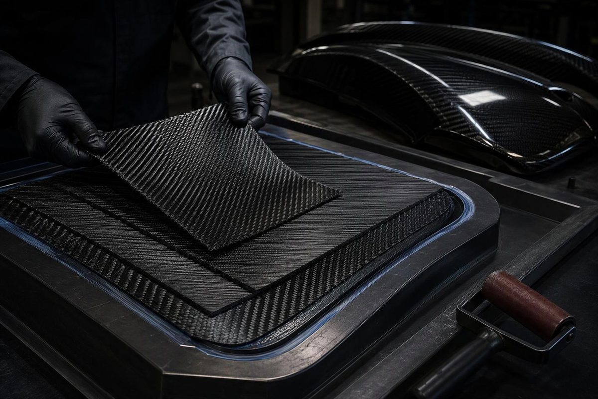
A composite layup is the arrangement of reinforcement layers—and the operation of placing those layers—to make a laminate. Each layer is a ply. For a carbon-fiber part, the plan must specify more than how many pieces of cloth to stack: material, fiber direction, ply order, coverage, resin system and consolidation all affect the finished material. Gurit’s Guide to Composites explains why composite properties are created during part fabrication, rather than simply inherited from purchased stock.
The practical sequence is: define the load path, write the ply schedule, prepare the kit and tool, place each ply, consolidate, cure and inspect. This guide covers fiber-reinforced thermoset laminates, including carbon/epoxy. The schedule is the link between the design and what actually goes into the mold.
Plan the laminate before cutting fabric
Start with the part’s geometry, supports and load-entry points. Identify tension, compression, bending and shear, along with service temperature, moisture exposure and repeated loading. Carbon fibers have their highest mechanical properties along their length; the resin transfers load between fibers and helps support them against buckling in compression. A laminate that works along one axis does not automatically work across it. Gurit, sections 1–2.
Choose and mark a reference direction on the drawing and tool. Call it 0°. Every ply angle is measured relative to that reference—not relative to whichever edge makes cutting convenient.
Distinguish the reinforcement forms:
- Unidirectional reinforcement: most structural fibers run in one direction; a 0° UD ply primarily reinforces that direction.
- Woven reinforcement: warp and weft provide two fiber directions. Record which yarn direction the stated angle refers to.
- Multiaxial reinforcement: one handled fabric can contain several stitched fiber layers. Its construction must be recorded, not reduced to “one layer of carbon.”
These distinctions follow Gurit’s fabric guidance. For material selection, see the separate guide to carbon-fiber weaves and reinforcement forms.
There is no generally safe answer to “How many plies do I need?” Thickness, orientation, geometry, joints and loads must be evaluated together. A safety-critical part needs an engineered laminate and a validation plan, not a layer count borrowed from a similar-looking component.
Write a ply schedule that can be built and checked
Use a layup sheet with these fields:
| Field | What to record |
|---|---|
| Reference and sequence | The 0° datum, angle convention and whether numbering starts at the tool or opposite face |
| Material | Exact reinforcement or prepreg designation, construction and areal weight |
| Each ply | Number, orientation, template and region covered |
| Discontinuities | Specified seams, overlaps, ply endings and local reinforcement |
| Core and interfaces | Core type, thickness, bedding or adhesive, and insert locations where applicable |
| Processing | Resin system, working limits, consolidation or debulk stages, bagging arrangement and cure schedule |
| Acceptance | Dimensions, thickness and inspection or test requirements |
Compact laminate notation describes orientation, but does not replace this sheet. For example, Gurit illustrates a UD stacking sequence written [0/+45/−45/90/−45/+45/0], starting at the top surface. The seven ply angles are:
0, +45, −45, 90, −45, +45, 0
If all plies have the same material and thickness, this example is symmetric and balanced: corresponding plies mirror one another about the central 90° ply, and +45° reinforcement is matched by −45° reinforcement. Symmetry helps limit bending or warping, while balance reduces shear coupling. Gurit’s laminate-notation discussion explains these concepts.
This is a notation example, not a recommended structural layup. Symmetry and balance do not establish strength, and symmetry does not guarantee a distortion-free molded part.
Prepare the tool and ply kit
Cut reinforcement and consumables before beginning a time-limited wet layup. Keep ply identification and orientation clear on templates, backing or kit records, without introducing unapproved markings into the laminate. Arrange the kit in placement order.
Check that the templates reach into corners without stretching the reinforcement away from its intended orientation. If the geometry requires seams or overlaps, specify them in the plan rather than improvising after resin is mixed.
Prepare the tool using the release-system manufacturer’s instructions. Confirm that the mold, release system and bagging materials suit the resin and cure temperature. Keep the sealing flange clean. Rehearse the operation and verify that the available labor can complete placement and bagging within the resin’s working window. These preparation controls are emphasized in the WEST SYSTEM vacuum-bagging manual, section 4.1. Use the protective clothing, gloves and ventilation required by the materials’ safety guidance.
Place and check each ply
The placement sequence remains controlled even though resin delivery differs by process:
- Wet layup: impregnate dry reinforcement during assembly, by hand or suitable equipment. Check epoxy compatibility rather than assuming every fabric binder works with epoxy. Wessex Resins’ wet-layup guidance.
- Infusion: assemble the reinforcement dry, add the process-specific flow and bagging materials, eliminate leaks, then introduce resin. Gurit, section 6.7.
- Prepreg: place reinforcement supplied with resin already incorporated, using the material supplier’s handling, consolidation and cure instructions. Gurit, sections 6.8–6.9.
For each ply, verify material, angle, coverage and contact before covering it with the next. In wet layup, work out trapped air and remove resin puddles without displacing the fibers. The WEST SYSTEM manual calls for checking each wetted fabric layer for excess epoxy and air pockets.
Watch particularly for bridging: reinforcement or bagging material spanning a corner instead of contacting it. The unsupported region can leave a void. Enough material, proper drape and careful placement are needed; vacuum is not a substitute for fitting the plies correctly. WEST SYSTEM, section 4.2.1.
Consolidate without starving the laminate
For a typical vacuum-bagged wet layup, the arrangement may be tool and release treatment → wet laminate → release fabric or peel ply → optional perforated release film → absorbent/breather material → sealed bag. The breather provides an air path to the vacuum port; absorbent material receives resin bleed. Exact materials and placement are process-specific. WEST SYSTEM’s bagging guidance.
Give the bag enough slack and pleats to reach recesses. Draw vacuum progressively, check contact and correct leaks before cure. For prepreg, use any intermediate debulk—temporary vacuum compaction—specified by the processing instructions.
Do not aim to remove as much resin as possible. Vacuum level, viscosity, time before gelation and release-film perforations affect resin bleed; excessive extraction can leave too little resin. WEST SYSTEM, section 4.2.2. Wessex recommends test panels to establish the bagging arrangement and pressure. Do not transfer a wet-layup bleeding arrangement automatically to prepreg or infusion.
Cure, then check against the plan
Follow the selected resin or prepreg’s cure instructions, including required pressure, temperature holds, cooling and post-cure. For vacuum-bagged wet laminates, monitor vacuum pressure and check for leaks throughout cure; do not treat a successful initial drawdown as the end of bag control. WEST SYSTEM, section 4.1.2.
Record the actual processing conditions and any deviations alongside the ply-placement record. Cure timing is not just “leave it until hard”; see the distinction between working time, demold and full cure.
After demolding, compare dimensions and thickness with the acceptance requirements and examine corners, seams and transitions for dry fabric, resin-rich regions, distortion and visible defects. Visual inspection can reveal processing problems, but hidden defects may require other nondestructive methods. Mechanical testing is used to establish design properties and verify manufacturing processes. Gurit, section 9.
A clean-looking surface is not proof that the intended laminate was built. The ply record, processing record and required inspection results must agree.