
How to Choose a Joint Without Compromising the Composite
Compare sleeves, clamps, inserts, bonded joints and bolted splices by load path, serviceability, failure modes and qualification evidence.
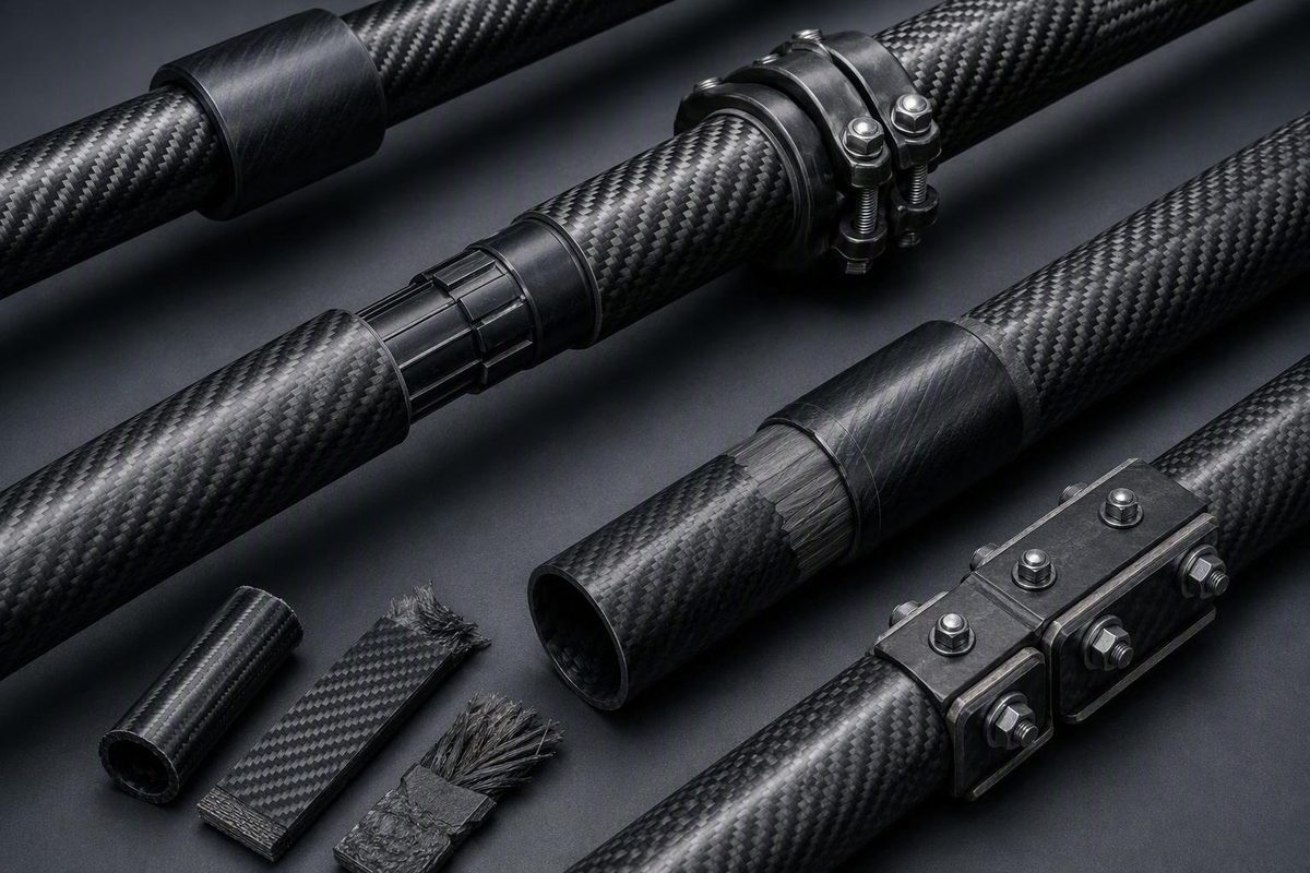
There is no universally best carbon-fiber joint. Choose the connection by tracing the actual load path, deciding whether it must come apart, and checking geometry, alignment, environment, inspection access, and manufacturing controls. A connector that fits the tube ID or matches the bolt pattern is only dimensionally compatible; structural suitability requires analysis and representative testing of the exact assembly.
Start here: match the joint to the assembly and service requirement
Begin by identifying what is being joined. Four categories call for different design logic:
- Tube-to-tube connectors join round, square, or rectangular members through sleeves, clamps, fittings, or frame nodes.
- Bonded laminate joints transfer load through an adhesive area between prepared composite surfaces.
- Structural splices or repairs restore or redirect load through an interrupted or damaged structural member.
- Carbon-to-metal interfaces connect the composite to brackets, bearings, threaded hardware, shafts, or custom fittings.
Do not treat these categories as interchangeable. A removable clamp for an adjustable tube may be useful without being suitable for a primary structural splice. Likewise, a bolted aircraft repair does not supply design allowables for a thin commercial tube.
The following table is a screening tool, not a complete design or qualification procedure.
| Joint configuration | Permanence and geometry | Principal advantages | Local risks and evidence to request |
|---|---|---|---|
| Bonded sleeve or insert | Usually permanent; straight tubes, tube ends, and compact interfaces | Transfers load over an area and can preserve a clean exterior | Investigate bond-end stresses, fit, preparation, voids, and cure variation. Request directional test loads, process records, and conditioned results. |
| External clamp | Removable or adjustable; commonly used around tubes | No adhesive cure; serviceable and repositionable | Poorly distributed pressure can damage a thin tube wall. Request clamp limits, contact geometry, and tube-specific tests. |
| Threaded insert | Insert usually permanent; attached hardware removable | Provides a controlled thread for studs, brackets, or rod ends | Investigate insert pull-out, local laminate damage, bond failure, and thread overload. Request ratings by load direction and installation controls. |
| Quick-release mechanism | Intended for repeated disassembly; telescoping or modular assemblies | Fast assembly and positive positioning when properly configured | Capacity depends on the specific tube, engagement, and lock. Request locking verification and cyclic, direction-specific test data. |
| Plate or gusset | Permanent or serviceable; frame nodes and square or rectangular members | Can connect several members and spread load across a larger node | Investigate peel, fastener bearing, eccentricity, and stiffness transitions. Request complete-node testing and joint-stiffness data. |
| Bolted splice | Serviceable in principle; laminates, webs, flanges, or specialized repairs | Positive mechanical load path and inspectable hardware | Holes interrupt fibers and require laminate-specific bearing, bypass, net-section, and delamination checks. Request applicable allowables and interaction analysis. |
| Bonded-and-fastened construction | Usually semi-permanent; laminates, fittings, and repairs | Provides more than one load-transfer mechanism | Load sharing and inspection can be complex. Request evidence for the combined construction rather than separate adhesive and fastener ratings. |
Before comparing hardware, write an initial joint specification that identifies:
- tension, compression, bending, torsion, vibration, and fatigue loads;
- load combinations, reversals, peaks, impacts, and expected cycles;
- required angular and axial alignment;
- tube ID, OD, wall thickness, laminate dimensions, and tolerances;
- available engagement length and external packaging space;
- relevant temperature, moisture, salt, and chemical exposure;
- access for assembly, inspection, and repair; and
- whether the joint is permanent, occasionally serviced, or repeatedly operated.
This definition should precede connector shopping. Otherwise, available hardware can end up determining the design before the load path is understood.
Common joints for carbon-fiber tubes
An internal sleeve fits inside two tubes and is commonly bonded in place to form a compact straight splice with a smooth exterior. Its apparent simplicity hides several variables: tube-ID tolerance, sleeve fit, alignment, engagement geometry, adhesive processing, and the way bending or torsion enters and leaves the overlap.
An external clamp surrounds the tube and provides a removable or adjustable connection without waiting for adhesive cure. Pressure must still be distributed over a suitable area because a poorly distributed clamp load can damage a thin-wall tube. Supplier-authored guidance describes this risk qualitatively but does not provide a universal pressure limit (overview of carbon-fiber tube connection methods).
Bonded inserts and end fittings create interfaces for brackets, studs, rod ends, and other hardware. Where a threaded attachment is needed, the thread is generally placed in a bonded or molded insert rather than cut directly into the carbon-fiber tube wall.
Quick-release and push-button mechanisms support repeated assembly, adjustment, or telescoping. They may use buttons, pins, ratchets, levers, or compression features. Their convenience does not establish structural capacity. Qualification must cover the specific tube, engagement, locking arrangement, loading direction, and expected operating cycles.
Plates and gussets are useful at nodes in square or rectangular frames. They may be bonded, mechanically attached, or both. Evaluate the node as a complete assembly because plate stiffness, attachment details, and offset load paths can shift critical demand into the tube wall.
Commercial hardware demonstrates the range of available mechanisms, not a performance ranking. Rock West’s catalog includes fixed, adjustable, angled, telescoping, ratcheting, and multi-adapter arrangements, along with locking components. Many listed parts are aluminum, stainless steel, or plastic rather than carbon fiber, so “for composite tubes” does not identify the connector material or establish structural qualification (Rock West composite-tube connector catalog).
Dimension check before ordering
- Tube inside diameter and outside diameter
- Wall thickness and laminate build
- Tube and connector tolerances
- Sleeve, insert, clamp, or pin engagement geometry
- Required angular range and indexing increments
- Locking method, secondary retention, and release access
- Clearance for adhesive, shims, coatings, or assembly variation
This check addresses fit. Strength, stiffness, fatigue life, and damage tolerance remain separate engineering questions.
Bonded joints: control geometry, bond ends, and process quality
A bonded joint transfers load over an area and can avoid drilling through load-carrying fibers. Its suitability still depends on the particular laminate, adhesive, geometry, surface preparation, cure, bondline quality, and service environment.
At minimum, the fabrication process should document:
- surface condition and preparation;
- adhesive identity, storage, and handling;
- fixture control and alignment;
- cure control;
- bondline consistency;
- contamination prevention;
- inspection method; and
- acceptance criteria.
There is no defensible universal adhesive, overlap length, bondline thickness, or cure schedule for every carbon-fiber joint. Those details must be established for the actual material pairing and load case.
A bounded example comes from a 2016 CFRP staircase-joint study in Composites Part B. The researchers first molded one stepped CFRP half and then remolded it with dry carbon-fiber laminates. The tested modifications added carbon-fiber covers and overlapped the dry-fiber half over the molded half.
The authors reported a 39% increase in total tensile load for the modified five-layer joint and a maximum joining efficiency of 59% for seven-layer CFRP. Cracks began near the joint ends in every tested configuration (2016 CFRP staircase-joint study).
That result does not establish that a staircase joint is best for another assembly. It does reinforce a practical design question: how will load transfer and stiffness change at the ends of the bonded region?
“Joining efficiency” also requires careful interpretation.
The cited public abstract and summary do not provide the complete specimen dimensions, specimen counts, variability, statistical analysis, or calculations behind the reported values. They also do not establish fatigue, impact, bending, compression, or environmental durability. The study is therefore useful for framing qualification questions, not for selecting dimensions for a different joint.
Bolted joints: preserve primary fibers and manage local load introduction
A fastener hole interrupts fibers and creates concentrated local loading. Fastener routing, laminate architecture, edge geometry, reinforcement, alignment, and fitting stiffness must therefore be evaluated as one system.
A 1996 NASA/U.S. Army Research Laboratory study provides a specialized example: a bolted repair joint for a pultruded carbon-epoxy rod-reinforced aircraft hat-section stringer. It was not an ordinary tube or a generic flat laminate. The design kept bolt holes out of the unidirectional rodpacks and routed fasteners through bias-ply webs and flanges.
The design required the stringer, fastener-pattern, and fitting centroids to align vertically within 10% of one another to limit eccentricity and local bending. It used an eight-ply doubler to address laminate bearing stress and flange edge distance, while a tapered 7050-T7452 aluminum fitting was intended to reduce peak loads in the first and last fastener rows (NASA bolted stringer-joint design and evaluation).
The central lesson is the sensitivity of predicted margin to the analysis assumption. With full bias-ply bearing capability assumed, the detailed model estimated an ultimate stringer strain of about 0.735%. Applying a conventional bearing-and-bypass interaction criterion reduced the estimate to about 0.39%. Neither value is an allowable for another joint; the difference shows how sharply an apparent margin can change with the selected interaction model and material allowable.
Configuration-specific checks illustrated by this case include:
- fitting yield;
- laminate bearing;
- bearing-and-bypass interaction;
- web-to-rodpack shear;
- fastener-row load distribution;
- net-section failure;
- eccentric bending; and
- compression buckling.
The general principle is to preserve primary fibers where practical and route local loads through laminate regions designed to accept them. The implementation still has to be derived for the actual structure.
Why tension and compression may produce different governing failures
No. A joint that performs well in tension cannot be assumed to perform equally well in compression. The two load directions can shift the governing failure into different parts of the assembly, and compression can introduce instability or buckling modes that a tensile test never exercises.
According to the NASA paper’s abstract, the tension design reached approximately 1.0% stringer strain and failed in the metal fitting at 166% of design ultimate load. The compression design failed in the carbon-epoxy specimen region at approximately 0.7% strain and 110% of panel design ultimate load. The program comprised only four specimens, tested at room temperature in as-fabricated condition without environmental conditioning; the authors also did not perform a finite-element buckling analysis for the compression specimen (NASA bolted stringer-joint study).
These figures are not general composite allowables, nor do they imply that a metal fitting should always be designed to fail first. They describe one specialized repair configuration.
A failure-path review should ask:
- Composite: Could bearing, net-section demand, splitting, delamination, crushing, or buckling govern?
- Adhesive: Could a bond end, interface, void, or contaminated region become critical?
- Fasteners: Could the fasteners fail, loosen, slip, tilt, or overload the surrounding laminate?
- Fitting: Could it yield, fracture, pry, or introduce eccentric load?
- Surrounding structure: Does the joint move the critical failure into an adjacent tube, skin, flange, or frame member?
Joint approval should be based on the weakest credible system-level mode for every relevant loading direction, not on the connector alone.
Carbon-to-metal fittings and commercial connectors
Carbon-to-metal interfaces commonly use bonded inserts, end fittings, external clamps, or mechanical fasteners. Depending on the design, the fitting may be aluminum, stainless steel, titanium, another composite, or an engineered plastic. Specify connector material and tube material separately.
Custom suppliers advertise metal-to-carbon connection parts, bearing housings, telescopic components, tie rods, plates, and joints made to customer drawings for machinery, frames, robotics, and marine applications. That establishes commercial availability, not verified structural performance (Carbonveneta joint and accessory services).
For a load-carrying application, request:
- rated loads for tension, compression, bending, torsion, and combined loading as applicable;
- joint stiffness, slip, and clearance under load;
- expected and observed failure modes;
- fatigue or cyclic-operation data;
- environmental conditioning used before testing;
- clamp, installation-torque, or assembly limits;
- design and test safety factors;
- test standards and specimen configuration;
- dimensional tolerances and fit requirements;
- tube laminate and wall thickness used in testing;
- fitting, fastener, and adhesive material specifications; and
- batch, process, and material traceability.
Also review material compatibility, moisture exposure, sealing, thermal movement, and electrical requirements for the particular assembly. These can matter independently of initial static strength, but the correct controls depend on the materials and service environment.
Catalogs and service pages are not sufficient for structural approval when they omit load ratings, test methods, failure modes, and environmental conditions. Product photographs, dimensional drawings, and promotional descriptions cannot fill those gaps.
Qualification checklist before a joint carries structural load
Treat this as a screening framework for building a project-specific qualification program—not as a substitute for applicable standards, certification rules, or engineering approval.
-
Identify the approval basis. Establish the governing industry standards, regulatory or customer requirements, certification basis, acceptance criteria, and the person or organization responsible for structural approval.
-
Define loads and environment. Document directions, combinations, peaks, cycles, vibration, impacts, temperature, moisture, chemicals, and required service life.
-
Document materials and geometry. Record the laminate schedule, tube wall, adhesive, fitting alloy or polymer, fasteners, hole preparation, surface condition, tolerances, and engagement geometry.
-
Analyze the complete load path. Include the composite, adhesive, inserts, fasteners, fittings, and adjacent structure. Check offsets, stiffness changes, and competing failure modes.
-
Build representative specimens. Test articles should reproduce the production laminate, adhesive, surface preparation, insert or fitting, dimensional variation, cure process, and assembly procedure. Idealized coupons alone may miss production-sensitive behavior.
-
Inspect fabrication quality. Define methods and acceptance limits for relevant conditions such as misalignment, voids, disbonds, delamination, hole damage, or incorrect fastener installation.
-
Test the relevant load cases. Candidate evaluations include static tension, compression, bending, torsion, fatigue, vibration, impact, and buckling. Select them from the real service case rather than treating every item as a universal prescription.
-
Condition specimens for service. Where exposure matters, represent the intended temperature, moisture, salt, or other environmental conditions rather than relying only on as-fabricated room-temperature results.
-
Set production acceptance controls. Define material traceability, process records, inspection frequency, allowable rework, rejection criteria, and change-control requirements.
A static tensile result does not establish fatigue life, impact tolerance, compression behavior, buckling resistance, or environmental durability. Each performance claim needs applicable analysis or testing.
Mechanical strength may not be the only requirement in an aerospace joint. A 2021 study used high-frequency electromagnetic measurements to examine adhesive and riveted carbon-composite joints because joint discontinuities and preferential current paths can affect electromagnetic behavior. The work addressed electromagnetic characterization and possible defect detection; it did not establish mechanical capacity or provide a supported quantitative adhesive-versus-rivet strength comparison (peer-reviewed electromagnetic characterization study).
The stop/go rule is straightforward: do not approve a structural carbon-fiber joint when the evidence consists only of dimensions, product images, qualitative claims, or one unconditioned static result. Proceed only when the responsible authority has evidence addressing the exact materials, geometry, environment, manufacturing process, inspection method, and loads.
Choose the joint by following the real load path rather than the lightest-looking connector or highest isolated test result. Preserve critical fibers where practical, introduce loads gradually, control alignment and local stresses, and qualify the actual assembly. Specialized aircraft splices and individual adhesive-joint experiments offer useful lessons, but neither supplies universal dimensions or allowables.
Can catalog dimensions tell me whether a carbon-fiber tube connector is structurally safe?
No. Dimensions can indicate whether a connector is likely to fit, but structural suitability also depends on the tube laminate and wall thickness, load direction, fitting stiffness, contact pressure, engagement, tolerances, environment, fatigue exposure, and governing failure mode. Request configuration-specific ratings, test methods, safety factors, and material traceability.
Can electromagnetic testing of a carbon-fiber joint replace mechanical testing?
No. Electromagnetic testing can characterize current paths or identify electrical discontinuities under a defined method, but it does not determine tensile strength, compression behavior, fatigue life, impact tolerance, or buckling resistance. Where both structural integrity and electrical behavior matter, they require complementary qualification methods.