
A Fusion Splicer Joins Optical Fiber, Not Carbon-Fiber Parts
What a fusion splicer does, why it cannot repair carbon-fiber laminates, and how optical splicing differs from composite bonding and welding.
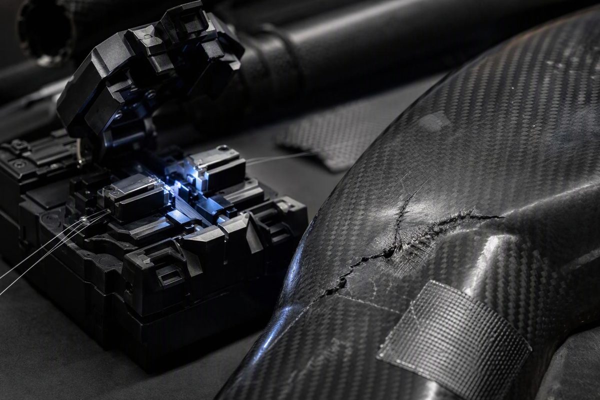
A fusion splicer is an optical-fiber joining machine—not a carbon-fiber repair tool. It aligns two optical fiber ends and usually uses an electric arc to fuse them together. The goal is to let light pass through the joint with minimal loss and reflection. The Fiber Optic Association (FOA) explains this process and its equipment.
If you are trying to join a carbon-fiber tube, reconnect reinforcement or repair a cracked laminate, an optical fusion splicer is the wrong equipment. The shared word fiber describes two different material functions: carrying light and carrying mechanical loads.
What a fusion splicer actually does
At a high level, optical splicing follows a controlled sequence:
- Strip the fiber’s protective coating.
- Clean the exposed fiber and precisely cleave its end.
- Place both ends in the splicer, which inspects and aligns them.
- Run the selected fusion program.
- Protect the finished joint with a sleeve or other splice protector.
The cleaver matters: poor end preparation can produce an unacceptable splice even with an automated machine. The splicer controls alignment, arc heating and the movement that brings the ends together. Its sleeve heater shrinks a protective sleeve around the finished joint; it is not a composite curing appliance. Follow the equipment manufacturer’s procedure for the specific fiber, splicer and protector. FOA’s fusion-splicing guide describes these steps and equipment requirements.
A displayed splice-loss estimate also is not acceptance testing of the installed optical link. Link testing compares measured insertion loss with the specified loss budget; an optical time-domain reflectometer (OTDR) can help evaluate individual splice events and locate faults where appropriate. FOA’s testing guidance distinguishes these tasks.
Why carbon-fiber repair is different
In a composite laminate, reinforcement direction largely determines mechanical performance. Repairing structural damage means creating a load path across the damaged area—not simply joining two visible ends.
Hexcel’s general composite-repair guide, published in 1999, describes structural repairs that replace damaged reinforcement and bond overlapping repair plies to the original laminate. It also warns that underlying damage can extend beyond the visible mark. An optical splicer neither rebuilds that layup nor establishes the strength of the repaired component.
For carbon/epoxy, there is another obstacle: cured epoxy is a thermoset. Its crosslinked polymer network prevents it from being melted back into a liquid for fusion joining. Excessive heating can degrade it instead. This does not mean cured epoxy stays equally stiff at every temperature; it means reheating is not a route back to uncured resin. TWI’s explanation of thermosets and thermoplastics describes the distinction.
For a load-bearing part, use a part-specific repair specification addressing damage extent, reinforcement, ply orientation, resin or adhesive, preparation, cure and inspection—not the general guide alone. A smooth-looking patch does not establish structural suitability.
What about “welding” carbon-fiber composites?
Some thermoplastic-matrix composites can be thermally welded. That is a separate joining process, not optical-fiber splicing.
For example, TWI demonstrated linear-friction welding of carbon-fiber-reinforced PEEK using an unreinforced PEEK interlayer. The work concerned a polymer-based joint between laminates, not end-to-end fusion of individual carbon filaments. It does not establish a repair method for carbon/epoxy.
Choose the joining route by the material and task:
- Optical fiber: use compatible splicing equipment and optical testing.
- Damaged carbon/epoxy: obtain a part-specific composite repair assessment.
- Thermoplastic composite: evaluate a welding process qualified for that matrix and joint geometry.
- Separate carbon-fiber components: compare bonded and mechanical joint designs against the required loads and service conditions.
The deciding question is not whether the material is called a fiber. It is what must remain continuous across the joint: an optical path or a structural load path.