
How Much Weight Does Carbon Fiber Really Save?
Representative density values put carbon roughly 29% lighter than fiberglass, with other values near 31%. Compare laminates and finished parts separately.
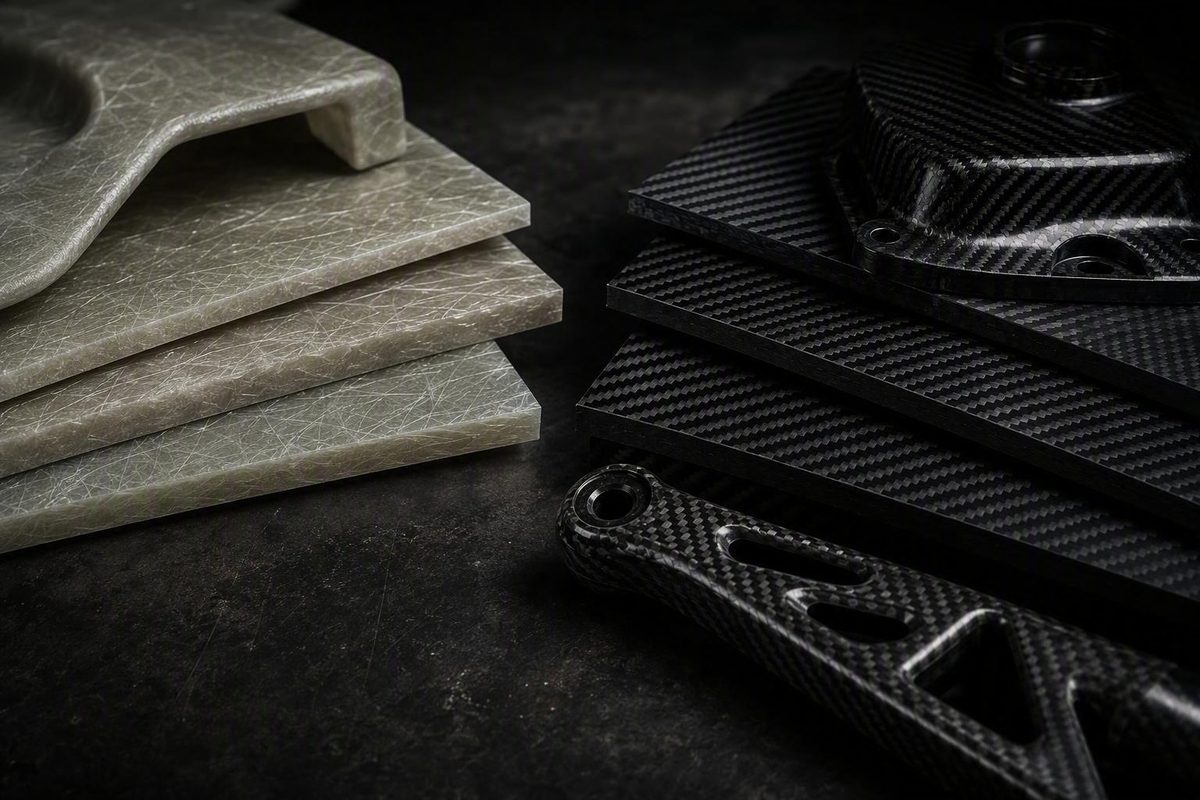
Method note: The calculations below use representative material values and transparent assumptions. They estimate mass; they do not certify a laminate or component for structural service.
The short answer: the percentage depends on what is being compared
Representative bare-fiber densities are about 1.78–1.80 g/cm³ for carbon fiber and 2.55–2.60 g/cm³ for E-glass. SAERTEX lists average fiber densities of 1.78 g/cm³ for carbon and 2.60 g/cm³ for glass Calculate fiber volume and laminate density – SAERTEX. These are representative averages, not specifications for every carbon or glass grade; for example, the SAERTEX laminate calculator uses 1.78 g/cm³ for carbon and 2.60 g/cm³ for glass.
That is the cleanest answer to “How much lighter is carbon fiber than fiberglass?” It is not a universal finished-part reduction. Four comparisons are often compressed into that one question:
- Equal fiber volume: Compare the mass of bare reinforcement fibers occupying the same volume.
- Equal cured-laminate dimensions: Compare carbon/resin and glass/resin laminates with the same area and thickness.
- Equal dry-fabric areal weight: Compare fabrics carrying the same grams per square meter before resin is added.
- Equal structural performance: Compare finished parts designed to meet the same stiffness, strength, deflection, impact, buckling, durability, and safety requirements.
Only the first comparison produces the straightforward 29%–31% range. Once resin, geometry, processing, and the rest of the component are included, the result changes.
Commercial comparison pages illustrate why published percentages need context. Spartec Composites says carbon fiber can be up to 15% lighter, but does not define matched grades, resin content, geometry, fiber fraction, or structural target. That figure is best treated as a commercially reported estimate rather than a universal conversion.
Tencom states that carbon fiber weighs about 70% as much as fiberglass. That is broadly consistent with the representative bare-fiber density ratio, but its comparison is framed around composite products and does not fully define the basis. The manufacturer’s 70% estimate should not automatically be applied to a cured panel or complete assembly.
| Comparison basis | What is held constant? | What the result can show | Typical interpretation |
|---|---|---|---|
| Bare fibers | Fiber volume | Intrinsic reinforcement-density difference | Carbon is about 29%–31% lighter than representative E-glass |
| Cured laminates | Laminate volume, resin system, and fiber fraction | Fiber-plus-resin density difference | Usually a smaller advantage than the bare-fiber figure |
| Equal-size panels | Area and cured thickness | Mass difference at specified laminate densities | Calculate with area × thickness × density |
| Equivalent-performance parts | Required structural and service performance | Potential redesign-enabled mass saving | Requires application-specific analysis and validation |
The correct percentage depends first on what is held constant. The following sections separate fiber, laminate, panel, and finished-part calculations so the estimate can be bounded rather than guessed.
Fiber density is not the same as laminate or finished-part weight
Composite terminology matters because each stage includes a different amount of material:
- Fiber is the carbon or glass filament itself.
- Dry reinforcement is fiber converted into fabric, tape, stitched material, mat, or another form without structural resin.
- Resin matrix is the cured polymer that binds the reinforcement, transfers load between fibers, maintains shape, and protects the fiber system.
- Cured ply is one consolidated layer of reinforcement and resin.
- Laminate is a stack of cured plies, often with different fiber orientations.
- Finished component is the laminate plus any core, coating, adhesive, insert, fastener, local reinforcement, sealant, edge treatment, and attached hardware.
At its simplest:
m_composite = m_fiber + m_resin
For a finished part:
m_part = m_laminate + m_core + m_adhesive + m_coatings + m_inserts + m_hardware + …
This explains why the bare-fiber ratio does not transfer directly to an assembly. A lighter skin may produce only a modest percentage reduction if much of the assembly mass is fixed core, paint, gelcoat, adhesive, fittings, or hardware.
Resin also narrows the raw-fiber density gap. Structural resin is much less dense than E-glass. When relatively low-density resin is combined with each reinforcement, the average density of both laminates moves toward the resin density. The glass laminate consequently receives a larger density reduction relative to its bare fiber than the carbon laminate does.
Dry-fabric weight is reinforcement weight only
Fabric is commonly sold by areal weight, such as 200 g/m² or 400 g/m². That figure normally describes the mass of dry reinforcement covering one unit of area. It is not the mass of a cured panel.
A 200 g/m² fabric contributes approximately 200 grams of reinforcement per square meter per ply, subject to product tolerance. The resin that remains in the cured laminate must be added when estimating finished-part weight, as must any core, permanent adhesive, coating, inserts, fasteners, and hardware.
Manufacturing consumption is a separate calculation. Peel ply, disposable flow media, hoses, mixing-pot residue, and excess resin left in feed lines may affect purchasing quantities and process yield, but they normally do not remain in the finished component. Feed features or surface materials should be included in part mass only when they are intentionally retained.
Equal fabric areal weight also does not mean equal cured ply thickness. If two dry fabrics each weigh 300 g/m², the carbon reinforcement occupies more fiber volume because carbon is less dense than E-glass. Tow size, stitching, weave, crimp, nesting, compaction pressure, and resin uptake can further change cured thickness.
Fiber weight fraction and fiber volume fraction therefore cannot be substituted casually. At the same reinforcement weight, carbon and glass can occupy different volumes; processing then changes how much resin and void volume remain in the laminate. A technical overview of composite constituent calculations also emphasizes that composite mass is fiber mass plus resin mass and that processing affects the resulting laminate.
Carbon grades vary, as do E-glass, S-glass, and other glass formulations. Resin systems also have different cured densities. A comparison that combines the density of bare E-glass, the density of cured CFRP sheet, and the weight of a complete fiberglass component mixes three measurement levels. A meaningful percentage must compare like with like.
Worked calculations for equal volume and equal-size panels
For a panel with fixed geometry:
m = A × t × \rho
where:
- m = mass
- A = panel area
- t = cured thickness
- \rho = cured laminate density
With consistent SI units:
m (kg) = A (m²) × t (mm) × \rho (g/cm³)
For a one-square-meter panel:
kg/m² = t (mm) × \rho (g/cm³)
A commercial guide reports broad finished-laminate ranges of approximately 1.4–1.9 g/cm³ for CFRP and 1.8–2.0 g/cm³ for GFRP, and uses the same sheet-weight relationship. These overlapping ranges are not a controlled carbon-versus-glass comparison, but they show why an unspecified laminate does not guarantee one fixed saving. The guide also distinguishes dry-fabric weight from cured sheet weight in its CFRP density and panel-weight calculation.
Example 1: equal volumes of bare fiber
Use:
- Carbon-fiber density: 1.78 g/cm³
- E-glass density: 2.60 g/cm³
For equal fiber volume:
m_carbon ÷ m_glass = 1.78 ÷ 2.60 = 0.6846
Carbon therefore has about 68.5% of the glass mass:
(1-0.6846) × 100 = 31.5\%
Under these assumptions, bare carbon fiber is approximately 31.5% lighter than bare E-glass. Using 1.80 and 2.55 g/cm³ instead gives about 29.4% less mass, which is why a representative 29%–31% range is more defensible than a single universal value.
Example 2: matched fiber-volume laminates
Now include resin. Assume:
- 50% fiber by volume
- 50% epoxy by volume
- Zero void content
- Carbon fiber: 1.78 g/cm³
- E-glass: 2.60 g/cm³
- Epoxy: 1.17 g/cm³
These are representative inputs listed by the SAERTEX calculator cited above. They are not specifications for every fiber or epoxy system.
For CFRP:
\rho_CFRP = (0.50 × 1.78) + (0.50 × 1.17)
\rho_CFRP = 0.89 + 0.585 = 1.475 g/cm³
Rounded:
\rho_CFRP ≈ 1.48 g/cm³
For GFRP:
\rho_GFRP = (0.50 × 2.60) + (0.50 × 1.17)
\rho_GFRP = 1.30 + 0.585 = 1.885 g/cm³
Rounded:
\rho_GFRP ≈ 1.89 g/cm³
The equal-dimension reduction is:
1-1.475 ÷ 1.885 = 0.2175
The CFRP laminate is therefore approximately 22% lighter under these assumptions.
This is a rule-of-mixtures result, not a universal measured value. It assumes the same resin, equal fiber volume, equal dimensions, and no voids. Different fiber fractions, resin densities, grades, architectures, and processing outcomes will move the answer.
Use real laminate data when available
Substitute the supplier’s cured-laminate density—or density measured from representative cured coupons—for generic values. Do not continue using a nominal constituent calculation once reliable process-specific laminate data exist.
Example 3: one-square-meter panels
Assume two cured laminate densities:
- Carbon laminate: 1.6 g/cm³
- Glass laminate: 1.9 g/cm³
For a 1 m² panel at 1 mm thickness:
m_carbon = 1 × 1 × 1.6 = 1.6 kg
m_glass = 1 × 1 × 1.9 = 1.9 kg
The difference is 0.3 kg/m². Relative to the glass panel:
1.9-1.6 ÷ 1.9 × 100 ≈ 15.8\%
At 2 mm:
| Laminate | Calculation | Mass |
|---|---|---|
| Carbon | 1 m² × 2 mm × 1.6 g/cm³ | 3.2 kg |
| Glass | 1 m² × 2 mm × 1.9 g/cm³ | 3.8 kg |
| Difference | 3.8 − 3.2 | 0.6 kg |
At 3 mm:
| Laminate | Calculation | Mass |
|---|---|---|
| Carbon | 1 m² × 3 mm × 1.6 g/cm³ | 4.8 kg |
| Glass | 1 m² × 3 mm × 1.9 g/cm³ | 5.7 kg |
| Difference | 5.7 − 4.8 | 0.9 kg |
The absolute saving rises linearly with thickness, but the percentage remains approximately 15.8% because area and the density ratio are unchanged.
These calculations establish mass only. They do not show that the panels have equal stiffness, strength, impact performance, stability, durability, or suitability for the same application.
How resin content and manufacturing method move the result
Fiber volume fraction, V_f, is the fraction of laminate volume occupied by fiber. Fiber weight fraction, W_f, is the fraction of laminate mass contributed by fiber.
They are not interchangeable:
V_f = m_f/\rho_f ÷ (m_f/\rho_f) + (m_r/\rho_r)
Because carbon and glass have different densities, the same fiber weight fraction produces different fiber volume fractions. At a nominal 50% fiber weight fraction, the Explore Composites example cited earlier estimates roughly 40% fiber volume for carbon and 30% for E-glass. The exact result depends on the selected fiber and resin densities.
Inputs for a nominal laminate estimate
A useful calculation needs, at minimum:
- Reinforcement areal weight
- Fiber density
- Resin density
- Fiber content by volume or weight
- Panel dimensions
- Number of plies
- Assumed void content
- Cured thickness or a method for estimating it
A manufacturer’s ply calculator uses reinforcement areal weight, fiber density, cured resin density, and resin content to estimate cured ply thickness and laminate density. It assumes zero void content and identifies its outputs as nominal guidance rather than guaranteed product properties. That limitation matters when using a nominal cured-ply calculation.
Why process matters
Open molding and hand lamination commonly retain more resin than tightly controlled vacuum processes. Vacuum bagging can compact the stack and remove some excess resin. Infusion controls resin flow through dry reinforcement, while prepreg begins with a specified resin content and is consolidated using its prescribed process.
Published planning ranges are not production guarantees. Epoxyworks, for example, gives typical fiber-weight-fraction ranges of 0.45–0.55 for hand lamination and 0.55–0.70 for vacuum bagging, while warning that calculated thicknesses are averages rather than engineered final specifications. These laminate-thickness assumptions should be replaced with shop-specific measurements whenever possible.
Excess retained resin adds mass and can increase cured thickness without adding fiber-direction reinforcement in proportion to that mass. That does not mean maximum fiber fraction is always best. Inadequate wet-out, porosity, bridging, fiber wash, wrinkles, or unsuitable consolidation can compromise the laminate.
Always state what is held constant:
- At fixed dimensions: Changing fiber fraction changes the constituent mix and laminate density.
- At fixed dry-fiber areal weight: Changing resin content changes total areal mass and usually cured thickness.
- At fixed fiber weight fraction: Carbon and glass occupy different fiber volumes.
- At fixed fiber volume fraction: Carbon and glass laminates contain different fiber masses and have different densities.
Nominal calculators may exclude process waste and additional resin retained in pots, hoses, feed channels, or disposable flow media. Keep three quantities separate:
- Material purchased
- Material consumed during processing
- Material cured into the finished component
Even fiber-fraction measurement requires care. A peer-reviewed investigation of PAN-based carbon/epoxy systems found that conventional ignition or digestion approaches can mismeasure carbon content because carbon fiber can oxidize and lose mass. The researchers developed a thermogravimetric method that accounted for this behavior, showing why carbon-fiber volume-fraction measurement may require a material-specific method.
When the predicted advantage is small—or purchasing, payload, balance, or compliance depends on it—make representative coupons with the intended fabric, resin, layup, cure, and compaction process. Record area, cured thickness, and mass:
\rho_measured = m ÷ A × t
Measure several coupons when process variability is material to the decision.
Equal thickness and equal performance are different comparisons
An equal-size comparison asks:
Which laminate weighs less if area and thickness remain the same?
An equivalent-performance comparison asks:
How should each laminate be designed to meet the same service requirements, and what does each validated design weigh?
Those are fundamentally different questions.
Carbon fiber’s stiffness and fiber-direction tensile capability may permit fewer plies or a thinner section when deflection or tensile loading governs. That redesign-enabled saving can differ from—and potentially exceed—the density saving for equal-thickness panels. There is no defensible universal “equal-strength” or “equal-stiffness” reduction for all parts.
A designer may be unable to thin a carbon laminate as much as a simple modulus or tensile calculation suggests. Other requirements can govern:
- Local or global buckling
- Compression strength
- Impact and indentation
- Minimum practical gauge
- Fastener bearing and pull-through
- Open-hole behavior
- Joint stiffness
- Insert loads
- Off-axis and transverse loads
- Surface durability
- Damage tolerance
- Manufacturing defects
- Inspection and repair requirements
Loading-mode dependence is demonstrated by a peer-reviewed comparison of vacuum-infused, biaxially knitted carbon/vinyl-ester and glass/vinyl-ester laminates intended for ship structures. The tested carbon system performed better in mainly fiber-dominated tension, while the glass system was equal or stronger in some compression and ballistic-impact tests. The results varied by loading mode and laminate system; the study did not measure finished-part weight saving, and the reinforcement systems were similar rather than identical.
| Comparison setup | Held constant | What it can establish | What it cannot establish by itself |
|---|---|---|---|
| Equal thickness | Area and thickness | Density and mass-per-area difference; properties at that thickness | Equal safety, life, deflection, or failure behavior |
| Equal mass | Total mass or areal mass | Which arrangement performs better at the same mass | Whether either design meets every service requirement |
| Equal stiffness | Stiffness or deflection target | Potential thickness and mass needed for that target | Equal strength, impact tolerance, buckling margin, or joint behavior |
| Equal strength | Defined load and failure criterion | Mass needed for that specific strength case | Equal stiffness, compression performance, durability, or damage tolerance |
“Equal strength” is incomplete unless the loading mode and failure criterion are named. Fiber-direction tension, open-hole compression, panel buckling, bolt bearing, and impact damage are separate checks.
For a non-structural cosmetic cover, equal dimensions may be the relevant comparison. For a beam, mast, hull panel, suspension component, pressure structure, or load-bearing body panel, the meaningful comparison is usually equal performance under defined load cases. That requires properties for the actual material system and a structural model appropriate to the component.
Why there is no safe cloth-for-cloth conversion ratio
An 8 oz fiberglass fabric cannot be converted into one universally valid lower carbon-fabric weight. “Replace it with 6 oz carbon” or “use 70% of the glass weight” may resemble the bare-fiber density ratio, but neither rule establishes an equivalent laminate.
Equal dry-cloth weight does not imply equal:
- Cured thickness
- Fiber volume
- Resin demand
- Stiffness
- Tensile strength
- Compression behavior
- Impact tolerance
- Buckling resistance
- Off-axis performance
- Hole and joint behavior
- Damage tolerance
Specialist forum discussions often raise this practical problem and reject a universal conversion. They document the concern but are not engineering authority for a numerical replacement rule. The Boat Design Net discussion itself points to project-specific issues such as laminate thickness, impact, and buckling.
Substitution checklist
Before changing reinforcement, define and check:
- Geometry: Skin dimensions, curvature, ribs, flanges, core, and unsupported spans
- Load direction: Fiber-aligned, transverse, shear, torsion, and combined loading
- Tension and compression: Evaluate both where applicable
- Deflection: Determine whether serviceability governs before failure
- Buckling: Check local and global stability
- Impact: Include realistic handling and service events
- Fatigue: Use application-appropriate data and loading spectra
- Holes and joints: Check open-hole performance, bearing, pull-through, and fastener loads
- Inserts: Assess local reinforcement and load introduction
- Minimum thickness: Account for manufacturing, handling, sealing, and surface requirements
- Resin compatibility: Confirm sizing, resin, cure, and environmental compatibility
- Exposure: Consider moisture, temperature, chemicals, ultraviolet exposure, and galvanic interfaces
- Safety factors: Apply those required by the design basis or applicable standard
- Manufacturing quality: Include realistic voids, wrinkles, resin variation, ply placement, and cure control
- Inspection and repair: Define how defects and service damage will be detected and restored
Supplier data should represent the actual fiber grade, fabric architecture, resin system, cure, fiber fraction, and laminate configuration. Generic fiber values are not substitutes for cured-lamina or laminate data.
Selective substitution can also alter the structure in less obvious ways.
A direct material substitution preserves the existing geometry while exchanging one reinforcement for another. A structural redesign changes the ply schedule, orientations, thickness, joints, or geometry to exploit the chosen material while rechecking every governing mode.
For load-bearing or safety-critical components, use qualified engineering review and physical testing appropriate to the consequences of failure. Nominal calculators estimate mass and thickness; they do not validate structural equivalence. The loading-mode study cited above demonstrates why tension data alone cannot establish compression, impact, or complete component performance.
When fiberglass may still be the better choice
Material selection is a tradeoff, not a ranking in which carbon is always the upgrade.
Carbon fiber is a strong candidate when minimum weight and high stiffness dominate and the design, process, budget, and validation program can exploit those properties. Fiberglass can remain preferable when the required performance can be achieved at lower material cost or when greater flexibility is useful. Commercial comparisons commonly present fiberglass as the less expensive option, although actual part cost depends on the design and production plan, not fabric price alone.
Impact, compression, and damage tolerance are configuration-specific. In the ship-oriented carbon/vinyl-ester versus glass/vinyl-ester study discussed earlier, tensile superiority in the tested carbon laminate did not become superiority in every compression and ballistic-impact test. That bounded result does not prove that fiberglass always performs better in impact.
Cost comparisons also need the correct denominator. Price per kilogram of fabric is not the same as cost per finished part or cost per kilogram saved. Compare supplier quotations, process yields, labor, tooling, inspection, repair provisions, and any secondary structure eliminated by the redesign. Spartec’s commercial comparison likewise describes fiberglass as potentially preferable when it meets requirements at lower production cost.
Assembly composition can dilute a laminate-level saving. If skins make up only part of a sandwich panel’s mass, the core, film adhesive, edge closeouts, paint, inserts, and hardware remain even when the skins become lighter. A 20% reduction in skin mass therefore produces less than a 20% reduction in total assembly mass.
| Decision factor | Carbon may be favored when… | Fiberglass may be favored when… | Validation needed |
|---|---|---|---|
| Weight sensitivity | Every unit of mass materially affects performance | Weight is secondary to cost or simplicity | Finished-part mass budget |
| Stiffness | Deflection governs and thinner carbon skins are feasible | Required stiffness is achievable without a meaningful weight penalty | Laminate and structural analysis |
| Tensile loading | Fiber-aligned tension dominates | Loads are multidirectional or another mode governs | Material-system tensile data |
| Compression or impact | Tested laminate meets all relevant criteria | A glass configuration better satisfies the event spectrum | Compression, impact, and damage tests |
| Budget | Weight saving justifies material and process expense | Performance can be met more economically | Total manufactured cost |
| Process control | Fiber fraction, cure, and ply placement are controlled | An established glass process is mature and consistent | Coupons and process qualification |
| Repair | A suitable inspection and repair system is available | Field familiarity or simpler material supply is important | Repair specification and tests |
| Required validation | Analysis and testing support redesign | Established, low-risk construction is preferable | Risk-based verification plan |
If a fiberglass part already meets its weight, stiffness, durability, cost, and production goals, replacing it solely because carbon fiber has a lower fiber density may add expense without creating a useful system-level advantage.
A practical workflow for estimating a real component
A defensible estimate starts by defining the comparison, not by selecting a percentage.
1. Define the target
Choose one or more:
- Equal external dimensions and thickness
- Equal mass
- Equal stiffness or deflection
- Equal strength under named load cases
- Redesign of an existing finished part
- Replacement meeting a complete performance specification
If several targets matter, state all of them. An equal-stiffness design is not automatically an equal-strength design.
2. Gather material inputs
Record:
- Carbon or glass grade
- Fabric, tape, mat, or prepreg style
- Fiber orientations
- Reinforcement areal weight
- Fiber density
- Cured resin density
- Resin system and cure
- Target fiber volume or weight fraction
- Assumed void content
- Supplier cured-ply thickness
- Supplier laminate density
- Relevant cured-lamina or laminate properties
Do not substitute generic fiber density for supplier laminate density. Fiber density belongs in a constituent calculation; cured-laminate density belongs in a fixed-panel mass calculation.
3. Gather geometry and assembly inputs
Record:
- Surface area
- Ply schedule by region
- Local doublers and reinforcements
- Nominal cured thickness
- Core type, thickness, and mass
- Adhesive and bonding area
- Gelcoat, primer, paint, or clearcoat
- Inserts and edge closeouts
- Fasteners, brackets, and attached hardware
- Trim allowance and finished dimensions
For curved parts, use developed surface area rather than projected area. Divide complex components into zones where thickness or ply count changes.
4. Calculate fiber and resin separately
For dry reinforcement:
m_f = A × n × AW
where AW is fabric areal weight and n is ply count.
If fiber weight fraction is known:
m_laminate = m_f ÷ W_f
m_r = m_laminate-m_f
If fiber volume fraction is known, calculate constituent volumes and masses from their densities. State any zero-void assumption explicitly.
Then add permanent non-laminate mass:
m_finished = m_f + m_r + m_core + m_adhesive + m_coating + m_inserts + m_hardware
Track disposable consumables and process losses separately.
5. Use the appropriate fixed-size method
If reliable cured-laminate density and thickness are available:
m = A × t × \rho
This is generally simpler than reconstructing density from constituent fractions. A constituent calculation remains useful as a cross-check and for estimating resin requirements.
For a structural redesign, do not multiply the fiberglass mass by the carbon-to-glass density ratio. Determine the carbon ply schedule and geometry from the structural requirements, then calculate the resulting mass.
6. Build low, nominal, and high cases
Use ranges for variables that are not yet controlled:
| Input | Low case | Nominal case | High case |
|---|---|---|---|
| Fabric areal weight | Lower accepted tolerance | Specified value | Upper accepted tolerance |
| Resin retained | Best qualified process | Production target | Resin-rich but accepted result |
| Cured thickness | Measured accepted low | Target | Measured accepted high |
| Voids | Qualified minimum | Expected level | Allowed maximum |
| Coating mass | Minimum finish | Standard finish | Approved appearance or repair allowance |
| Hardware and adhesive | Drawing minimum | Bill-of-material estimate | Installation allowance |
Do not treat excess voids as a beneficial low-mass condition. Every case must remain within the accepted quality specification.
7. Make and weigh representative coupons
Use the intended:
- Reinforcement batch and architecture
- Resin and mix ratio
- Tool surface
- Layup method
- Bagging or infusion stack
- Cure cycle
- Compaction pressure
- Finishing system
Measure coupon area, mass, and thickness at enough locations to characterize the laminate. Compare measured density with the nominal calculation and investigate meaningful discrepancies before projecting production weight.
8. Keep special structures out of oversimplified calculators
A monolithic-laminate tool is not automatically suitable for sandwich structures, thick bonded assemblies, pultrusions, molded compounds, hybrid laminates, or products with substantial surface layers. SAERTEX limits its calculator to simple or monolithic fabric laminates and states that it is not suitable for sandwich structures or special products.
For sandwich panels, calculate each skin, permanent adhesive layer, core, closeout, insert, coating, and fitting separately. For hybrids, calculate each reinforcement type by ply or zone.
Reusable input checklist
- [ ] Comparison target clearly defined
- [ ] Existing part mass verified
- [ ] Carbon and glass grades identified
- [ ] Fabric styles and areal weights identified
- [ ] Resin system and cured density documented
- [ ] Fiber-fraction basis stated as weight or volume
- [ ] Void assumption stated
- [ ] Surface area and thickness mapped by zone
- [ ] Full ply schedules available
- [ ] Core, adhesive, coatings, inserts, and hardware included
- [ ] Process waste tracked separately from finished mass
- [ ] Low, nominal, and high cases calculated
- [ ] Supplier cured-laminate data obtained
- [ ] Representative coupons manufactured and weighed
- [ ] Structural checks completed for redesigns
- [ ] Physical testing planned where consequences require it
Compact worksheet
| Item | Fiberglass option | Carbon option |
|---|---|---|
| Comparison target | ||
| Area by zone | ||
| Ply count and orientations | ||
| Reinforcement areal mass | ||
| Fiber density | ||
| Resin density | ||
| Fiber volume or weight fraction | ||
| Cured laminate density | ||
| Cured thickness | ||
| Fiber mass | ||
| Resin mass | ||
| Core and adhesive mass | ||
| Coating mass | ||
| Inserts and hardware | ||
| Predicted finished mass | ||
| Measured coupon density | ||
| Verified finished mass | ||
| Governing structural checks |
The final answer has two separate parts. Bare carbon fiber is roughly 29%–31% lighter than representative E-glass at equal fiber volume, based on representative constituent densities. The difference between cured, equal-size laminates is usually smaller and must be calculated from the actual fiber-resin system and processing assumptions.
A validated structural redesign may save more by allowing a thinner or otherwise optimized carbon part, but carbon cloth is not a drop-in fiberglass replacement. Define the comparison basis, calculate laminate and added mass separately, and verify the estimate with supplier data or cured samples before making a structural decision.
Frequently asked questions
Is carbon fiber 30% lighter than fiberglass?
Approximately—if the comparison is between equal volumes of representative bare carbon fiber and E-glass fiber. Typical values of about 1.80 g/cm³ for carbon and 2.55 g/cm³ for fiberglass make carbon roughly 29% lighter; other representative values produce a result near 31%. These are typical average densities rather than universal product specifications.
That does not mean every carbon laminate or finished part is 30% lighter. Resin content, fiber fraction, thickness, process, core, coatings, inserts, and hardware change the result.
How do I calculate the weight of a carbon-fiber or fiberglass panel?
For a fixed-size panel:
m = A × t × \rho
With area in square meters, thickness in millimeters, and density in grams per cubic centimeter:
m (kg) = A (m²) × t (mm) × \rho (g/cm³)
For example, a 2 m² panel that is 1.5 mm thick and has a laminate density of 1.6 g/cm³ weighs:
2 × 1.5 × 1.6 = 4.8 kg
Add permanent cores, adhesives, coatings, inserts, fasteners, local reinforcements, and hardware separately. Use measured or supplier laminate density whenever possible.
Does carbon-fiber fabric weight include resin?
Not when the product is specified by dry-fabric areal weight. A 200 g/m² dry carbon fabric contains approximately 200 grams of reinforcement per square meter before resin, subject to product tolerance.
Prepreg is different because resin is already incorporated. Distinguish its total prepreg areal weight, fiber areal weight, and resin content. Finished-part weight may also include permanent coatings, adhesive, core, inserts, and hardware.
Can I replace fiberglass cloth with a lighter carbon cloth at a fixed ratio?
No universal ratio is technically defensible. Equal cloth weight does not guarantee equal thickness, stiffness, tensile or compression strength, impact response, buckling resistance, resin demand, or joint performance.
Use cured-laminate data for the actual reinforcement and resin system, evaluate all governing loads and failure modes, and test the proposed construction where appropriate. Load-bearing and safety-critical substitutions require application-specific engineering rather than a density-based conversion.
Does vacuum bagging make a composite laminate lighter than hand layup?
It can produce a lighter or thinner laminate for the same dry reinforcement by improving compaction and reducing excess retained resin. It does not guarantee a particular saving. Bag pressure, bleed strategy, fabric architecture, resin viscosity, workmanship, cure, and target fiber fraction all affect the result.
Compare cured coupons made by the two intended processes while holding reinforcement area and ply schedule constant. Their measured mass and thickness provide a more reliable process-specific answer than a generic percentage.