
When a Carbon-Fibre Driveshaft Is Worth the Cost—and How to Specify One
Mass reduction or extra critical-speed margin must solve a real need; check torque, RPM, balance, joints, heat, fitment and certification.
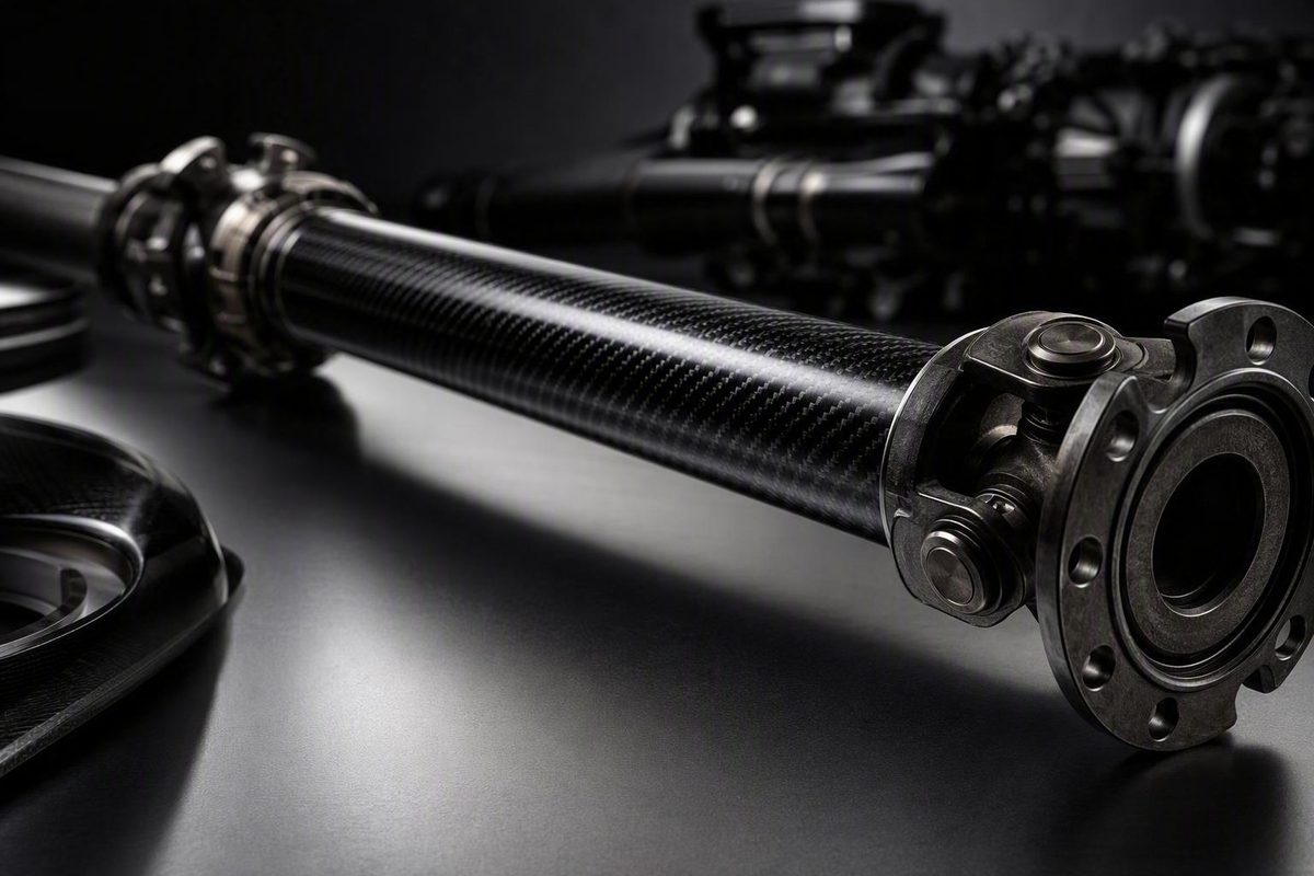
A carbon-fibre propshaft is worth considering when lower rotating mass, a long-span one-piece layout or additional critical-speed margin solves a defined engineering problem. It is not an automatic performance upgrade. The correct choice depends on torque, maximum shaft RPM, span, tube geometry, joints, driveline angles, shock loading, heat and clearance.
For many road or harsh-duty vehicles, steel remains the economical, conventionally repairable option. Aluminium often occupies the lighter, mid-priced middle ground. Choose carbon fibre only when the complete assembly—not merely the tube material—has documented limits suitable for the installation.
The short answer: who should consider a carbon-fibre propshaft?
“Propshaft” and “driveshaft” are regional names for the rotating assembly that transmits torque from the gearbox or transmission to the differential. In some markets, the same component is called a tailshaft. The finished assembly includes more than its tube: end fittings, universal joints or flanges, any required slip connection, fasteners and balance correction all affect suitability.
| Vehicle or duty | Conditional assessment | What should decide it |
|---|---|---|
| Daily road use | Possible, but often difficult to justify | Installed cost, heat, impact exposure and serviceability |
| Circuit racing | Potentially worthwhile | Complete rotating mass, shaft RPM, balance and sustained temperature |
| Repeated drag launches | Potentially suitable | Peak torque, shock loading, joints, bond design and certification |
| Circle-track racing | Commercially available | Rules, length, included yoke, inspection and replacement budget |
| Long-wheelbase vehicle | Potentially valuable | Span, critical speed, tube diameter and tunnel clearance |
| High-RPM one-piece conversion | Strong candidate if properly validated | Critical-speed margin, angles, clearance and exact fitment |
Carbon fibre is most compelling where a lighter assembly, a longer unsupported span or greater critical-speed potential materially helps the design. Commercial products are offered for circle-track, drag, high-power street, long-span and one-piece-conversion applications, but a product category does not validate a particular installation.
Steel may remain preferable where low purchase cost, conventional repairability, constant heavy loads or harsh service matter most. Aluminium can remove mass at a lower price than carbon fibre, although its diameter, strength and speed limits must still suit the application. A driveline workshop’s broad comparison places steel at the repairable, low-cost end, aluminium in the middle and carbon fibre as the premium option, while emphasising that selection depends on the vehicle and duty cycle (GJ Drivelines’ material overview).
No material wins every duty cycle. Identify the problem—mass, speed, span, packaging or compliance with racing rules—before choosing the material.
Carbon fibre vs steel vs aluminium: the practical trade-offs
| Criterion | Steel | Aluminium | Carbon fibre |
|---|---|---|---|
| Complete assembly mass | Commonly highest, but configuration-dependent | Commonly below comparable steel | Often low, but joints and ends matter |
| Rotational inertia | Depends on mass distribution and diameter | Configuration-dependent | Configuration-dependent |
| Purchase price | Usually lowest | Commonly mid-range | Usually highest |
| Corrosion behaviour | Requires protection | Does not rust like steel; inspect interfaces | Tube does not rust; metal ends and interfaces still matter |
| Impact tolerance | Generally suited to harsh service | Can dent or deform | Impact or abrasion may cause difficult-to-assess damage |
| Conventional repairability | Usually best | Application-dependent | Structural tube damage generally leads to replacement |
| Critical-speed potential | Can constrain long spans | May improve on steel | Commonly marketed as higher, but design-specific |
| Typical duty | Road, heavy load and harsh service | Road and moderate performance | Racing, high RPM, long span and packaging-led builds |
Reducing shaft mass reduces rotational inertia, meaning less energy is needed to accelerate the shaft itself. That does not create engine horsepower or guarantee a measurable improvement in acceleration. Any vehicle-level result depends on the complete change in mass and mass distribution, gearing, vehicle mass, traction and the shafts being compared.
Compare complete assemblies and, if available, the manufacturer’s mass-moment-of-inertia data rather than assuming that the lightest listed weight automatically produces the lowest inertia.
Critical speed is another common reason to investigate carbon fibre. Suppliers market composite shafts as offering higher critical-speed potential than similarly sized metal shafts, but “carbon fibre” is not an RPM rating. Length, outside diameter, wall construction, laminate stiffness, end fittings, joints, runout, balance and installed alignment all affect the safe margin.
The recurring disadvantages are practical: premium price, sensitivity to strikes and abrasion, internal damage that may not be obvious at the surface, product-specific resin and adhesive temperature limits, and replacement rather than conventional straightening or welding after structural damage. Carbon fibre also does not remove maintenance concerns around U-joints, flanges, fasteners or metal interfaces.
Compare complete assemblies rather than isolated listing weights. One short Fast Shafts race product is listed at approximately 7 lb without a yoke, whereas PST’s 15 lb figure belongs to a different high-power drag configuration. The figures do not establish a like-for-like weight advantage because the lengths, diameters, joints, yokes and intended duties differ.
Specify the shaft as a system—not by horsepower alone
Horsepower is not enough to size a propshaft. Specification must address both torsional capacity and dynamic stability.
Critical speed is the rotational speed at which shaft instability and whipping become a risk. A shaft can therefore have sufficient static torque strength yet be unsuitable for its intended RPM or span. There is no useful universal RPM table for carbon-fibre propshafts because diameter, length, laminate, joints, boundary conditions and balance vary.
Use this worksheet before requesting a quote:
- Vehicle make, model, year and chassis configuration
- Engine and transmission type
- Transmission output or slip-yoke specification
- Differential input flange or yoke specification
- Maximum power and peak torque
- Maximum propshaft RPM—not merely engine RPM
- Tyre size and final-drive ratio
- Intended use: road, circuit, drag, circle track, towing or mixed
- Launch method and expected shock loading
- U-joint series, flange pattern and fastener requirements
- Required slip travel
- Operating angles at static ride height and through suspension travel
- Shaft span and the supplier’s specified measurement points
- Minimum tunnel, crossmember and exhaust clearance
- Expected temperature near the tube and bonded ends
- Required sanctioning-body certification
Length conventions are not interchangeable. One supplier may request the centre-to-centre distance between universal joints, while another uses a transmission-seal-to-rear-joint-centre dimension. Follow the selected supplier’s drawing and measure the vehicle in the stated condition; do not transfer a dimension from another listing.
PST’s order form, for example, requests seal-to-centre length, rear U-joint size, maximum RPM, maximum horsepower and transmission type. Its longer-shaft surcharges are instead divided into centre-to-centre length bands. These inputs begin the specification process; they do not independently prove that the finished shaft is safe.
A long one-piece conversion needs additional checks. Confirm that the proposed tube can pass through the tunnel without contacting the body, crossmembers, safety loops or exhaust throughout suspension and powertrain movement. Verify operating angles, slip travel, balance and an application-specific critical-speed margin. Replacing a two-piece system with one piece changes the system geometry as well as its material.
Read ratings and test figures without comparing unlike numbers
| Evidence label | What it can establish | What to check |
|---|---|---|
| Independent experiment | Results for the tested specimen and conditions | Geometry, loading, protocol and relevance |
| Published product specification | Seller’s stated configuration or limit | Exact part number, options and inclusions |
| Manufacturer claim | Supplier’s asserted performance | Test report, specimen and operating conditions |
| Owner anecdote | One user’s experience | Vehicle, setup, duration and confounding factors |
A continuous operating rating defines permitted service under stated conditions. A proof or integrity test checks whether a specimen survives a specified load. A destructive test identifies failure under its particular protocol. A certification result applies only within the certifier’s rules and the tested or registered configuration. These figures cannot automatically substitute for one another.
PST illustrates the distinction. Its product page describes a shaft for applications up to 3,000 hp, a bidirectional 3,000 ft-lb tube-integrity test and a separately independently tested SFI configuration said to withstand 2,800 ft-lb. These are three different statements, not interchangeable safe operating limits. The page also says assemblies are computer-balanced to less than 1/8 ounce-inch variance, but it does not establish that figure as a universal industry comparison standard (PST’s 3.75-inch carbon-fibre drag-shaft listing).
Before ordering, request:
- Maximum operating torque and maximum RPM for the exact length, tube, laminate, joints and end fittings
- Whether each number is continuous, transient, proof, destructive or calculated
- Test specimen, protocol, loading direction, environment and failure criterion
- Balance tolerance, measurement units and balancing speed
- Certification body, standard, expiration or registration requirements, and covered configuration
- Installation requirements, bolt specifications and driveline-angle limits
- Temperature limit and required exhaust clearance or shielding
- Inspection schedule and objective removal-from-service criteria
- Warranty terms and exclusions for racing, impact, heat, overspeed and installation error
Descriptions such as “rule legal,” “stronger” and “safer” are incomplete unless the governing rules, compared configuration and test basis are identified. One retailer, for example, calls a Wiles shaft “rule legal” without naming the applicable series or sanctioning body. The buyer still needs written confirmation that the exact part and installation satisfy the relevant rules.
What independent testing establishes—and what it does not
A 2018 SAE Baja project provides useful but tightly bounded evidence. Its specific filament-wound carbon-fibre/epoxy shaft was reported to be 60% lighter and 8.5% stronger in torsion than the vehicle’s OEM steel comparison. It was a 300 mm shaft for a 10 hp all-terrain vehicle, designed mainly for torsion in a fully floating arrangement with negligible axial and bending loads. The laminate had a stated 25% fibre-volume fraction and used a winding sequence constrained by the available machine (the 2018 MATEC conference paper).
The study also observed delamination, matrix agglomeration, fibre pull-out and matrix cracking after torsional loading. Its results do not predict fatigue, impact resistance, critical speed or road durability for a longer, faster and more heavily loaded automotive shaft.
A KTH Formula Student project examined carbon-composite tubes with adhesively bonded steel end fittings. Its single- and double-lap specimens exceeded the project’s 600 Nm design load before the test equipment reached its limit. Because the specimens did not fail, the work did not establish ultimate strength. It also did not investigate fatigue or creep (the KTH end-fitting and adhesive-joint project).
Together, these projects show that a properly designed composite tube and bonded joint can transmit meaningful torque in specific motorsport applications. They also show why laminate and joint design matter. They do not establish universal superiority, long-term durability or a guaranteed vehicle-level performance gain.
Construction, bonded end fittings, and quality control
A filament-wound tube begins with continuous carbon filaments fed from spools through alignment guides. Resin is applied before the winding head places the fibres around a mandrel at controlled angles and speed. Layers build to the specified thickness, after which the tube is cured. Machine Service describes winding angle, speed and layer thickness as controlled process variables (MSI’s driveshaft-tube winding overview).
The visible carbon tube is only one part of the design. Fibre angle influences how loads are carried in torsion and along the shaft. Layer sequence, resin system, fibre volume, cure quality, wall thickness and diameter affect torsional and bending behaviour. Different manufacturers can therefore produce materially different shafts under the same broad “carbon fibre” label.
The complete load path runs through:
- The composite tube
- The tube-to-end-fitting adhesive joint
- Metal end fittings
- U-joints, CV joints or flanges
- Yokes, splines and fasteners
- The balanced installed assembly
Commercial products illustrate the variation. Action Machine lists a tube with a 3.810-inch outside diameter and 0.155-inch wall, forged 6061-T6 aluminium yokes and Spicer 1350-series U-joints. Its custom length is listed up to 68 inches centre-to-centre, while slip and flange yokes are not included (Action Machine’s custom 1350-series product). PST’s high-power drag configuration instead lists a bonded proprietary 7075 forged-aluminium tube yoke. These are attributed product configurations, not generic carbon-shaft specifications.
A static torque test can demonstrate that a particular specimen survived a particular load. It does not, by itself, establish long-term resistance to fatigue, vibration, moisture, creep or thermal cycling.
Damage, heat, inspection, and replacement decisions
Treat these events or symptoms as warnings:
- Stone strike or other substantial impact
- Deep scratch, gouge or abrasion
- Crushed, frayed or exposed fibres
- Suspected delamination or a changed surface contour
- Damage, movement or discolouration near a bonded end
- Exhaust contact or overheating
- Missing balance weight or signs of contact
- New vibration, noise or runout
The Baja test specimens, for example, exhibited several internal and interfacial damage mechanisms after torsional loading. The available evidence does not provide a universal owner-level pass/fail method or inspection interval for every carbon-fibre propshaft.
As a conservative safety measure, remove the vehicle from service after a substantial impact, severe scrape, overheating event or unexplained vibration until the assembly has been assessed under the manufacturer’s criteria by a qualified driveline or composite specialist. Do not sand, fill, wrap or rebalance a suspect shaft as a generic repair.
PST’s general material guidance describes a broken carbon-fibre shaft as non-repairable and requiring replacement rather than conventional driveline repair (PST’s steel, aluminium and carbon-fibre comparison). That is a supplier position, not proof that every surface mark has caused structural failure. It does, however, explain why the manufacturer’s damage criteria matter: composite tube damage cannot be corrected through the straightening or welding methods used on some metal shafts.
Thermal limits are product-specific. PST lists 350°F as the maximum temperature tolerance for its 3.75-inch drag product and warns that prolonged street use may require exhaust shielding or clearance changes. Do not transfer that number to another resin system or shaft model.
Some suppliers describe a failed carbon tube as “brooming” into fibres rather than producing large metal fragments. That does not make failure harmless.
Price examples and the real cost of installation
The following representative prices were checked against the listed pages on 11 September 2026. They are examples, not a universal market range; prices, stock, options and specifications can change.
| Product example | Price checked | Listed configuration | Important qualifications |
|---|---|---|---|
| Fast Shafts crate late-model, 37.5 in | $717 | 2.25-in OD; approximately 7 lb | No yoke; no torque or safe-speed rating shown (retailer listing) |
| PST 3.75-in drag shaft | $1,338 base | 15 lb; 1350/1480 options | $50 SFI option; $100–$400 length surcharges above 53 in (manufacturer listing) |
| QA1 selected circle-track products | About $810–$1,430 | Various dirt-modified and late-model lengths | Price varies by category and stated slip-yoke inclusion |
| QA1 visible SFI-labelled Mustang products | About $2,280 | Vehicle-specific listings | Confirm exact fitment and certification scope (QA1 catalogue) |
The Fast Shafts price and weight exclude the yoke, and the listing supplies no torque or safe-speed rating. PST’s base price includes neither every possible length nor every option. Its listed length surcharges begin at $100 for shafts from 53 to 59 inches and reach $400 above 70 inches, measured centre-to-centre.
QA1’s visible listings showed selected circle-track configurations from approximately $809.95 to $1,429.95 and SFI-labelled Mustang products at $2,279.95. Some product titles explicitly included a slip yoke while others did not. That wording does not prove that every unmentioned component is excluded, so compare the full bill of materials with the supplier.
Budget for the installed system, including:
- U-joints or CV joints
- Slip yoke, flange yoke or companion flange
- New fasteners and retaining hardware
- Balancing and runout checks
- Certification label, registration or periodic renewal
- Length and custom-machining charges
- Shipping and protective packaging
- Installation labour
- Tunnel, crossmember, safety-loop or exhaust modifications
- Heat shielding
- Initial and recurring inspections
- Replacement exposure after impact or structural damage
Before paying, verify current price, lead time, exact fitment, included parts, complete assembly weight, torque and RPM limits, certification scope, warranty and inspection instructions directly with the supplier.
A carbon-fibre propshaft is the rational choice when documented mass reduction or additional critical-speed margin solves a real requirement and the supplier can validate the exact assembly’s torque, RPM, balance, joints, thermal limit and certification. If lower cost, conventional repairability or harsh-duty tolerance matters more, steel or aluminium may provide better value.
Before ordering, confirm:
- Exact installed length using the supplier’s convention
- Peak torque and maximum shaft RPM
- Tube diameter, wall construction and clearance
- Joint, yoke, flange and slip requirements
- Driveline angles and suspension movement
- Temperature and exhaust shielding
- Balance tolerance and critical-speed margin
- Certification, warranty and inspection criteria
- Complete assembly mass and geometry
- Total installed cost—not the tube price or headline material claim
Can a damaged carbon-fibre propshaft be repaired?
Do not assume that it can. PST’s published material comparison treats a broken carbon-fibre shaft as a replacement item rather than a conventionally repairable component. Research specimens have also exhibited delamination, fibre pull-out and matrix cracking, showing why visible appearance alone may not describe the full damage.
A minor-looking mark is not automatically structural failure, but neither should it be covered with a generic patch or cosmetic finish. Use the shaft manufacturer’s inspection and replacement criteria and obtain qualified assessment after a significant impact, scrape or overheating event.
Does a lighter propshaft add horsepower?
No. It does not increase the engine’s power output. Lower shaft mass can reduce rotational inertia, so less energy is required to accelerate the shaft itself, but the vehicle-level effect depends on the complete change in mass and mass distribution, gearing, traction and test conditions. Shaft weight alone does not justify a guaranteed acceleration or wheel-power claim.
Is a torque proof-test figure the same as the safe operating rating?
No. A proof or integrity test shows that a defined specimen survived a defined test load. A safe operating rating must account for repeated loads, RPM, geometry, joints, shock, temperature, fatigue and an appropriate margin.
Ask the supplier to label each figure as continuous operating, transient, proof, destructive, calculated or certification-related. Do not treat a horsepower claim, proof-test result and certification figure as interchangeable limits.
What is the difference between a propshaft and a driveshaft?
In this context, there is usually no functional difference. “Propshaft,” “driveshaft” and, in some markets, “tailshaft” refer to the rotating assembly transmitting torque from the gearbox or transmission to the differential.
Terminology can vary in other driveline layouts. Confirm whether a supplier’s quoted product includes the complete balanced assembly or only the tube and specified end components.